


MCF51QE128 MCU Series Reference Manual, Rev. 3
Freescale Semiconductor 99
Get the latest version from freescale.com
Chapter 5 Resets, Interrupts, and General System Control
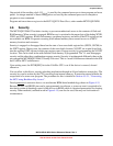
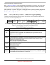
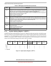
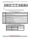
5.7.2 System Reset Status Register (SRS)
This high page register includes read-only status flags to indicate the source of the most recent reset. When
a debug host forces reset by setting CSR2[BDFR], none of the status bits in SRS are set. Writing any value
to this register address clears the COP watchdog timer without affecting the contents of this register. The
reset state of these bits depends on what caused the MCU to reset.
1
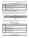
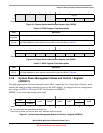
IRQIE
IRQ Interrupt Enable. This read/write control bit determines whether IRQ events generate an interrupt request.
0 Interrupt request when IRQF set is disabled (use polling).
1 Interrupt requested when IRQF is set.
0
IRQMOD
IRQ Detection Mode. This read/write control bit selects edge-only detection or edge-and-level detection. The
IRQEDG control bit determines the polarity of edges and levels detected as interrupt request events. See
Section 5.4.1.2, “Edge and Level Sensitivity” for more details.
0 IRQ event on falling edges or rising edges only.
1 IRQ event on falling edges and low levels or on rising edges and high levels.
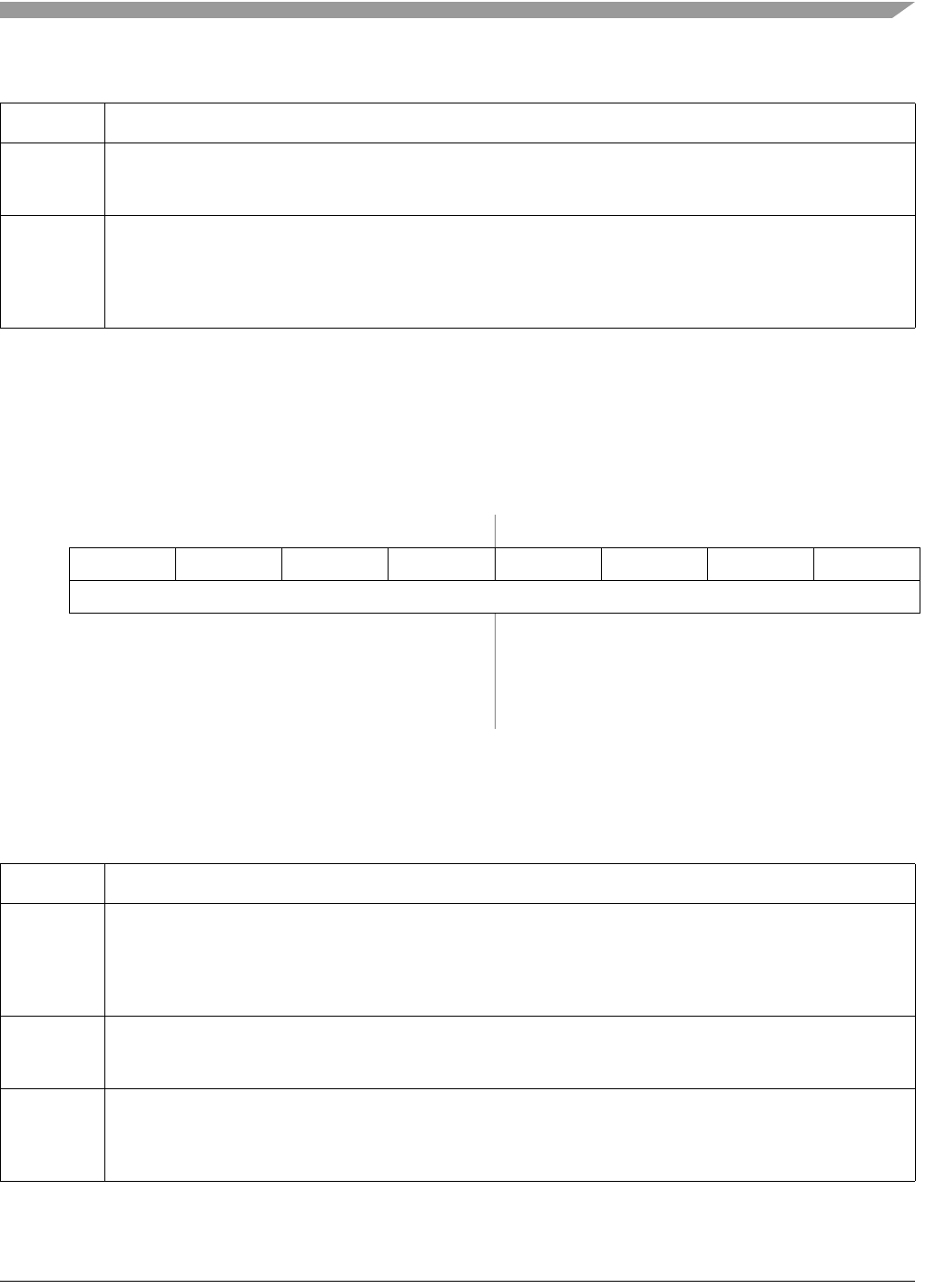
76543210
R POR PIN COP ILOP ILAD 0 LVD 0
W Writing any value to SRS address clears COP watchdog timer.
POR:
10000010
LVD:
u0000010
Any other
reset:
0Note
1
Note
1
Note
1
Note
1
000
1
Any of these reset sources active at the time of reset entry causes the corresponding bit(s) to be set; bits corresponding to
sources not active at the time of reset entry are cleared.
Figure 5-2. System Reset Status (SRS)
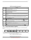
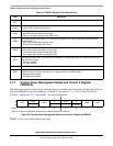
Table 5-3. SRS Register Field Descriptions
Field Description
7
POR
Power-On Reset. Reset was caused by the power-on detection logic. Because the internal supply voltage was
ramping up at the time, the low-voltage reset (LVD) status bit is also set to indicate that the reset occurred while
the internal supply was below the LVD threshold.
0 Reset not caused by POR.
1 POR caused reset.
6
PIN
External Reset Pin. Reset was caused by an active-low level on the external reset pin.
0 Reset not caused by external reset pin.
1 Reset came from external reset pin.
5
COP
Computer Operating Properly (COP) Watchdog. Reset was caused by the COP watchdog timer timing out. This
reset source is blocked if COPE is cleared.
0 Reset not caused by COP timeout.
1 Reset caused by COP timeout.
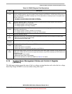
Table 5-2. IRQSC Register Field Descriptions (continued)
Field Description