


Chapter 18 Version 1 ColdFire Debug (CF1_DEBUG)
MCF51QE128 MCU Series Reference Manual, Rev. 3
Freescale Semiconductor 411
Get the latest version from freescale.com
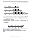
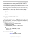
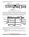
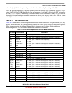
18.4.3.1 Begin Execution of Taken Branch (PST = 0x05)
PST is 0x5 when a taken branch is executed. For some opcodes, a branch target address may be loaded
into the trace bufer (PSTB) depending on the CSR settings. CSR also controls the number of address bytes
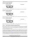
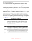
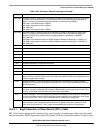
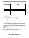
0x08–0x0B Indicates the number of data bytes to be displayed as DDATA on subsequent processor clock cycles.
This marker value is driven as the PST one processor clock cycle before the data is displayed on
DDATA. The capturing of peripheral bus data references is controlled by CSR[DDC].
0x08 Begin 1-byte data transfer on DDATA
0x09 Begin 2-byte data transfer on DDATA
0x0A Reserved
0x0B Begin 4-byte data transfer on DDATA
0x0C–0x0F Indicates the number of address bytes to be displayed as DDATA on subsequent processor clock
cycles. This marker value is driven as the PST one processor clock cycle before the address is
displayed on DDATA. The capturing of branch target addresses is controlled by CSR[BTB].
0x0C Reserved
0x0D Begin 2-byte address transfer on DDATA (Displayed address is shifted right 1: ADDR[17:1])
0x0E Begin 3-byte address transfer on DDATA (Displayed address is shifted right 1: ADDR[24:1])
0x0F Reserved
0x10–0x11 Reserved
0x12 Completed execution of 2 sequential instructions
0x13 Completed execution of 3 sequential instructions
0x14 Completed execution of 4 sequential instructions
0x15 Completed execution of 5 sequential instructions
0x16 Completed execution of 6 sequential instructions
0x17 Completed execution of 7 sequential instructions
0x18 Completed execution of 8 sequential instructions
0x19 Completed execution of 9 sequential instructions
0x1A Completed execution of 10 sequential instructions
0x1B This value signals there has been a change in the breakpoint trigger state machine. It appears as a
single marker for each state change and is immediately followed by a DDATA value signaling the new
breakpoint trigger state encoding.
0x1C Exception processing. This value signals the processor has encountered an exception condition.
Although this is a multi-cycle mode, there are only two PST = 0x1C values recorded before the mode
value is suppressed.
0x1D Emulator mode exception processing. This value signals the processor has encountered a debug
interrupt or a properly-configured trace exception. Although this is a multi-cycle mode, there are only
two PST = 0x1D values recorded before the mode value is suppressed.
0x1E Processor is stopped. This value signals the processor has executed a STOP instruction. Although this
is a multi-cycle mode since the ColdFire processor remains stopped until an interrupt or reset occurs,
there are only two PST = 0x1E values recorded before the mode value is suppressed
.
0x1F Processor is halted. This value signals the processor has been halted. Although this is a multi-cycle
mode since the ColdFire processor remains halted until a BDM go command is received or reset
occurs, there are only two PST = 0x1F values recorded before the mode value is suppressed
.
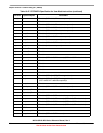
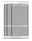
Table 18-26. Processor Status Encodings (continued)
PST[4:0] Definition