


MCF51QE128 MCU Series Reference Manual, Rev. 3
50 Freescale Semiconductor
Get the latest version from freescale.com
Chapter 3 Modes of Operation
3.7 Wait Modes
3.7.1 Wait Mode
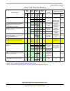
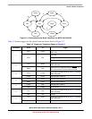
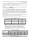
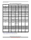
Wait mode is entered by executing a STOP instruction after configuring the device as per Table 3-1. Upon
execution of the STOP instruction, the CPU enters a low-power state in which it is not clocked.
The V1 ColdFire core does not differentiate between stop and wait modes. Both are stop from the core’s
perspective. The difference between the two is at the device level. In stop mode, most peripheral clocks
are shut down. In wait mode, they continue to run.
XCSR[ENBDM] must be set prior to entering wait mode if the device is required to respond to BDM
commands once in wait.
When an interrupt request occurs, the CPU exits wait mode and resumes with exception processing,
beginning with the stacking operations leading to the interrupt service routine.
3.7.2 Low-Power Wait Mode (LPwait)
Low-power wait mode is entered by executing a STOP instruction while the MCU is in low-power run
mode and configured per Table 3-1. In the low-power wait mode, the on-chip voltage regulator remains in
its standby state as in the low-power run mode. In this state, the power consumption is reduced to a
minimum that allows most modules to maintain funtionality. Power consumption is reduced the most by
disabling the clocks to all unused peripherals by clearing the corresponding bits in the SCGC registers.
Low-power run mode restrictions also apply to low-power wait mode.
If the LPWUI bit is set when the STOP instruction is executed, the voltage regulator returns to full
regulation when wait mode is exited. The ICS can be set for full speed immediately in the interrupt service
routine.
If the LPWUI bit is cleared when the STOP instruction is executed, the device returns to low-power run
mode.
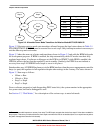
Any reset exits low-power wait mode, clears the LPR bit, and returns the device to normal run mode.
3.7.2.1 BDM in Low-Power Wait Mode
If a device is in low-power wait mode, a falling edge on an active BKGD/MS pin exits low-power wait
mode, clears the LPR and LPRS bits, and returns the device to normal run mode.
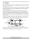
3.8 Stop Modes
One of three stop modes is entered upon execution of a STOP instruction when SOPT1[STOPE] is set. The
SOPT1[WAITE] bit must be clear, else wait mode is entered. In stop3 mode, the bus and CPU clocks are
halted. If the ENBDM bit is set prior to entering stop4, only the peripheral clocks are halted. The ICS
module can be configured to leave the reference clocks running. See Chapter 12, “Internal Clock Source
(S08ICSV3),” for more information.