


MCF51QE128 MCU Series Reference Manual, Rev. 3
178 Freescale Semiconductor
Get the latest version from freescale.com
Chapter 8 Interrupt Controller (CF1_INTC)
• Memory-mapped off-platform slave module
— 64-byte space located at top end of memory: 0x(FF)FF_FFC0–0x(FF)FF_FFFF
— Programming model accessed via the peripheral bus
— Encoded interrupt level and vector sent directly to processor core
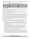
• Support of 30 peripheral I/O interrupt requests plus seven software (one per level) interrupt
requests
• Fixed association between interrupt request source and level plus priority
— 30 I/O requests assigned across seven available levels and nine priorities per level
— Exactly matches HCS08 interrupt request priorities
— Up to two requests can be remapped to the highest maskable level + priority
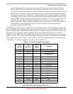
• Unique vector number for each interrupt source
— ColdFire vector number = 62 + HCS08 vector number
— Details on IRQ and vector assignments are device-specific
• Support for service routine interrupt acknowledge (software IACK) read cycles for improved
system performance
• Combinatorial path provides wake-up signal from wait and sleep modes
8.1.3 Modes of Operation
The CF1_INTC module does not support any special modes of operation. As a memory-mapped slave
peripheral located on the platform’s slave bus, it responds based strictly on the memory addresses of the
connected bus.
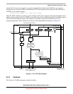
One special behavior of the CF1_INTC deserves mention. When the device enters a wait or stop mode of
operation and certain clocks are disabled, there is an input signal that can be asserted to enable a
purely-combinational logic path for monitoring the assertion of an interrupt request. After a request of
unmasked level is asserted, this combinational logic path asserts an output signal which is sent to the clock
generation logic to re-enable the internal device clocks to exit the low-power mode.
8.2 External Signal Description
The CF1_INTC module does not include any external interfaces.
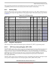
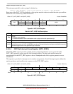
8.3 Memory Map and Register Definition
The CF1_INTC module provides a 64-byte programming model mapped to the upper region of the
16 Mbyte address space. All the register names are prefixed with INTC_ as an abbreviation for the full
module name.
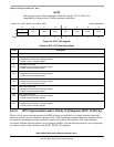
The programming model is referenced using 8-bit accesses. Attempted references to unimplemented
addresses or with a non-supported access type (for example, a write to a read-only register) generate a bus
error termination.