


Timer/PWM Module (S08TPMV3)
MCF51QE128 MCU Series Reference Manual, Rev. 3
Freescale Semiconductor 349
Get the latest version from freescale.com
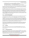
17.4.1.3 Counting Modes
The main timer counter has two counting modes. When center-aligned PWM is selected (CPWMS = 1),
the counter operates in up/down counting mode. Otherwise, the counter operates as a simple up counter.
As an up counter, the timer counter counts from 0x0000 through its terminal count and continues with
0x0000. The terminal count is 0xFFFF or a modulus value in TPMxMODH:TPMxMODL.
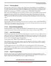
When center-aligned PWM operation is specified, the counter counts up from 0x0000 through its terminal
count and then down to 0x0000 where it changes back to up counting. The terminal count value and
0x0000 are normal length counts (one timer clock period long). In this mode, the timer overflow flag
(TOF) becomes set at the end of the terminal-count period as the count changes to the next lower count
value.
17.4.1.4 Manual Counter Reset
The main timer counter can be manually reset at any time by writing any value to either TPMxCNTH or
TPMxCNTL. Resetting the counter in this manner also resets the coherency mechanism in case only half
of the counter was read before resetting the count.
17.4.2 Channel Mode Selection
Provided CPWMS is cleared, TPMxCnSC[MSnB,MSnA] determine the basic mode of operation for the
corresponding channel. Choices include input capture, output compare, and edge-aligned PWM.
17.4.2.1 Input Capture Mode
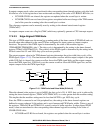
With the input-capture function, the TPM can capture the time an external event occurs. When an active
edge occurs on the pin of an input-capture channel, the TPM latches the contents of the TPM counter into
the channel-value registers (TPMxCnVH:TPMxCnVL). Rising edges, falling edges, or any edge may be
chosen as the active edge that triggers an input capture.
In input capture mode, TPMxCnVH and TPMxCnVL are read-only.
When either half of the 16-bit capture register is read, the other half is latched into a buffer to support
coherent 16-bit accesses in big-endian or little-endian order. The coherency sequence can be manually
reset by writing to TPMxCnSC.
An input capture event sets a flag bit (CHnF) that may optionally generate a CPU interrupt request.
While in BDM, the input capture function works as configured. When an external event occurs, the TPM
latches the contents of the TPM counter (frozen because of the BDM mode) into the channel value registers
and sets the flag bit.
17.4.2.2 Output Compare Mode
With the output-compare function, the TPM can generate timed pulses with programmable position,
polarity, duration, and frequency. When the counter reaches the value in the channel-value registers of an
output-compare channel, the TPM can set, clear, or toggle the channel pin.