


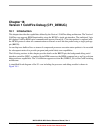
Timer/PWM Module (S08TPMV3)
MCF51QE128 MCU Series Reference Manual, Rev. 3
Freescale Semiconductor 351
Get the latest version from freescale.com
• If CLKSB and CLKSA are not cleared, the registers are updated after both bytes are written, and
the TPM counter changes from TPMxMODH:TPMxMODL − 1 to TPMxMODH:TPMxMODL. If
the TPM counter is a free-running counter, the update is made when the TPM counter changes from
0xFFFE to 0xFFFF.
17.4.2.4 Center-Aligned PWM Mode
This type of PWM output uses the up/down counting mode of the timer counter (CPWMS=1). The output
compare value in TPMxCnVH:TPMxCnVL determines the pulse width (duty cycle) of the PWM signal
while the period is determined by the value in TPMxMODH:TPMxMODL. TPMxMODH:TPMxMODL
should be kept in the range of 0x0001 to 0x7FFF because values outside this range can produce ambiguous
results. ELSnA determines the polarity of the CPWM output.
Pulse width = 2 × (TPMxCnVH:TPMxCnVL)
Period = 2 × (TPMxMODH:TPMxMODL); TPMxMODH:TPMxMODL = 0x0001–0x7FFF
If the channel-value register, TPMxCnVH:TPMxCnVL, is zero or negative (bit 15 set), the duty cycle
is 0%. If TPMxCnVH:TPMxCnVL is a positive value (bit 15 clear) and is greater than the non-zero
modulus setting, the duty cycle is 100% because the duty cycle compare never occurs. This implies the
usable range of periods set by the modulus register is 0x0001 through 0x7FFE (0x7FFF if you do not need
to generate 100% duty cycle). This is not a significant limitation. The resulting period would be much
longer than required for normal applications.
All zeros in TPMxMODH:TPMxMODL is a special case that should not be used with center-aligned
PWM mode. When CPWMS is cleared, this case corresponds to the counter running free from 0x0000
through 0xFFFF. When CPWMS is set, the counter needs a valid match to the modulus register somewhere
other than at 0x0000 in order to change directions from up-counting to down-counting.
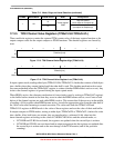
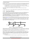
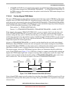
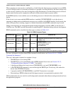
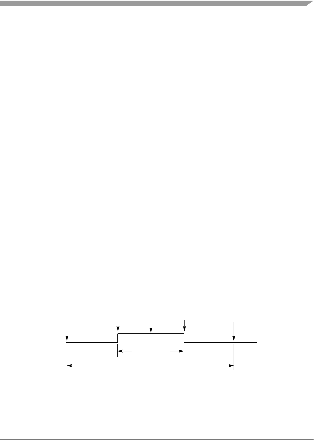
The output compare value in the TPM channel registers (times two) determines the pulse width (duty
cycle) of the CPWM signal (Figure 17-16). If ELSnA is cleared, a compare occurring while counting up
negates the CPWM output signal and a compare occurring while counting down asserts the output. The
counter counts up until it reaches the modulo setting in TPMxMODH:TPMxMODL, then counts down
until it reaches zero. This sets the period equal to two times TPMxMODH:TPMxMODL.
Figure 17-16. CPWM Period and Pulse Width (ELSnA=0)
Center-aligned PWM outputs typically produce less noise than edge-aligned PWMs because fewer I/O pin
transitions are lined up at the same system clock edge. This type of PWM is also required for some types
of motor drives.
Period
Pulse Width
Count=
Count= 0
Count=
Output
Compare
(Count Down)
Output
Compare
(Count Up)
TPMxCHn
2 x TPMxMODH:TPMxMODL
2 x TPMxCnVH:TPMxCnVL
TPMxMODH:TPMxMODLTPMxMODH:TPMxMODL