


MCF51QE128 MCU Series Reference Manual, Rev. 3
26 Freescale Semiconductor
Get the latest version from freescale.com
Chapter 1 Device Overview
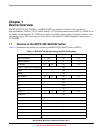
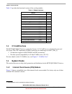
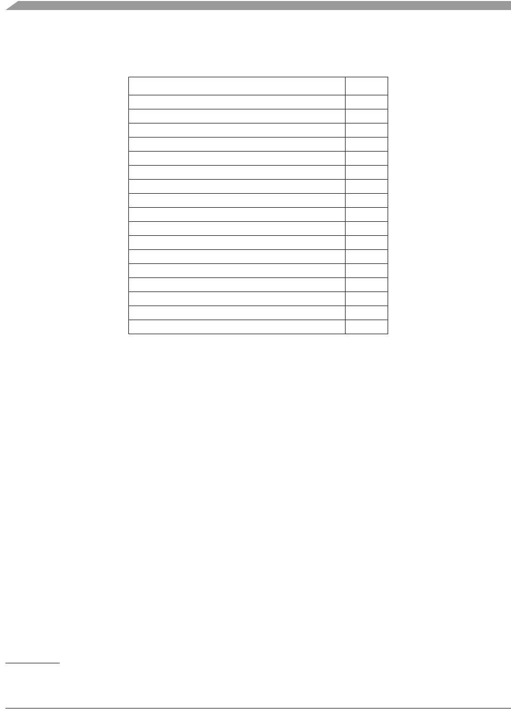
Table 1-2 provides the functional version of the on-chip modules
1.3 V1 ColdFire Core
The MCF51QE128/64/32 devices contain the Version 1 (V1) ColdFire core optimized for area and
low-power. This CPU implements ColdFire instruction set architecture revision C (ISA_C):
• No hardware support for MAC/EMAC and DIV instructions
1
• Provides upward compatibility to all other ColdFire cores (V2–V5)
For more details on the V1 ColdFire core, see Chapter 7, “ColdFire Core”.
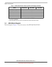
1.4 System Clocks
This section discusses on-chip clock generation and distribution for the MCF51QE128/64/32 devices.
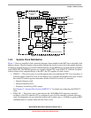
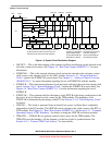
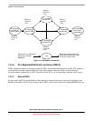
1.4.1 Internal Clock Source (ICS) Module
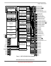
Figure 1-2 shows a simplified view of the internal clock source module. For clarity, only one of three
available FLL modules is shown.
Table 1-2. Module Versions
Module Version
Analog Comparator (ACMP) 4
Analog-to-Digital Converter (ADC) 1
V1 ColdFire Core (CF1_CORE) 1
V1 ColdFire Interrupt Controller (CF1_INTC) 1
V1 ColdFire Debug Module (CF1_DEBUG) 1
General Purpose I/O (GPIO) 2
Inter-Integrated Circuit (IIC) 2
Internal Clock Source (ICS) 3
Keyboard Interrupt (KBI) 2
Low-Power Oscillator (OSCVLP) 1
Port Set/Clear (PSC) 1
Rapid GPIO (RGPIO) 1
Real-Time Counter (RTC) 1
Serial Communications Interface (SCI) 4
Serial Peripheral Interface (SPI) 3
Timer Pulse Width Modulator (TPM) 3
Voltage Regulator (PMCx)1
1. These operations can be emulated via software functions.