


Analog-to-Digital Converter (S08ADC12V1)
MCF51QE128 MCU Series Reference Manual, Rev. 3
234 Freescale Semiconductor
Get the latest version from freescale.com
11.4.7 MCU Stop3 Mode Operation
Stop mode is a low power-consumption standby mode during which most or all clock sources on the MCU
are disabled.
11.4.7.1 Stop3 Mode With ADACK Disabled
If the asynchronous clock, ADACK, is not selected as the conversion clock, executing a stop instruction
aborts the current conversion and places the ADC in its idle state. The contents of ADCRH and ADCRL
are unaffected by stop3 mode. After exiting from stop3 mode, a software or hardware trigger is required
to resume conversions.
11.4.7.2 Stop3 Mode With ADACK Enabled
If ADACK is selected as the conversion clock, the ADC continues operation during stop3 mode. For
guaranteed ADC operation, the MCU’s voltage regulator must remain active during stop3 mode. Consult
the module introduction for configuration information for this MCU.
If a conversion is in progress when the MCU enters stop3 mode, it continues until completion. Conversions
can be initiated while the MCU is in stop3 mode by means of the hardware trigger or if continuous
conversions are enabled.
A conversion complete event sets the COCO and generates an ADC interrupt to wake the MCU from stop3
mode if the ADC interrupt is enabled (AIEN = 1).
NOTE
The ADC module can wake the system from low-power stop and cause the
MCU to begin consuming run-level currents without generating a system
level interrupt. To prevent this scenario, software should ensure the data
transfer blocking mechanism (discussed in Section 11.4.4.2, “Completing
Conversions) is cleared when entering stop3 and continuing ADC
conversions.
11.4.8 MCU Stop2 Mode Operation
The ADC module is automatically disabled when the MCU enters stop2 mode. All module registers
contain their reset values following exit from stop2. Therefore, the module must be re-enabled and
re-configured following exit from stop2.
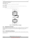
11.5 Initialization Information
This section gives an example that provides some basic direction on how to initialize and configure the
ADC module. You can configure the module for 8-, 10-, or 12-bit resolution, single or continuous
conversion, and a polled or interrupt approach, among many other options. Refer to Table 11-7,
Table 11-8, and Table 11-9 for information used in this example.