


MCF51QE128 MCU Series Reference Manual, Rev. 3
46 Freescale Semiconductor
Get the latest version from freescale.com
Chapter 3 Modes of Operation
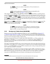
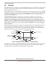
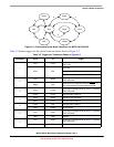
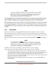
Figure 3-2. Allowable Power Mode Transitions for Mission Mode MCF51QE128/64/32
Figure 3-2 illustrates mission mode state transitions allowed between the legal states shown in Table 3-1.
PTA5/IRQ/TPM1CLK/RESET must be asserted low to exit stop2. Only interrupt assertion is necessary to
exit the other stop and wait modes.
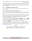
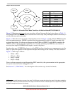
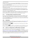
Figure 3-3 takes the same set of states and transitions shown in Figure 3-2 and adds the BDM halt mode
for development purposes. If BDM is enabled, the chip automatically shifts LP modes into their fully
regulated equivalents. If software or debugger set the LPR bit in SPMSC2 while BDM is enabled, the
LPRS bit reflects the fact that the regulator is not in standby. Similarly, the PPDF does not indicate a
recovery from stop2 if ENBDM forced stop4 to occur in its place.
1
Stated another way, if ENBDM has been set via the BDM interface, then the power management controller
keeps (or puts) the regulator in full regulation despite other settings in the contrary. The states shown in
Figure 3-3 then map as follows:
• LPrun ⇒ Run
•LPwait ⇒ Wait
• Stop3 ⇒ Stop4
• Stop2 ⇒ Stop4
From a software perspective (and disregarding PMC status bits), the system remains in the appropriate
low-power state, and can be debugged as such.
See Section 3.7, “Wait Modes,” for a description of the various ways to enter halt mode.
1. This can have subtle impacts on recovery from stop. The IRQ input can wake the device from stop4 if it has been enabled for
that purpose. That same pin wakes the device from stop2 even when the IRQ is not enabled (there is an asynchronous path to
the power management controller in that state).
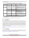
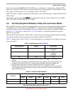
Mode Regulator State
Run Full On
Wait Full On
Stop4 Full On
LPrun Standby
LPwait Standby
Stop3 Standby
Stop2 Partial Power Off
Stop3
Stop2
LPwait
Stop4
Wait
Run LPrun