


MCF51QE128 MCU Series Reference Manual, Rev. 3
204 Freescale Semiconductor
Get the latest version from freescale.com
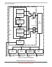
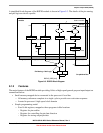
Chapter 9 Rapid GPIO (RGPIO)
• BCHG_LOOP: In this loop, a bit change instruction was executed using the GPIO data byte as the
operand. This instruction performs a read-modify-write operation and inverts the addressed bit. A
pulse counter is decremented until the appropriate number of square-wave pulses have been
generated.
• SET+CLR_LOOP: For this construct, two store instructions are executed: one to set the GPIO data
pin and another to clear it. Single-cycle NOP instructions (the tpf opcode) are included to maintain
the 50% duty cycle of the generated square wave. The pulse counter is decremented until the
appropriate number of square-wave pulse have been generated.
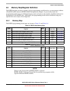
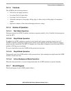
The square-wave output frequency was measured and the relative performance results are presented in
Table 9-11. The relative performance is stated as a fraction of the processor’s operating frequency, defined
as f MHz. The performance of the BCHG loop operating on a GPIO output is selected as the reference.
NOTE
The square-wave frequency is measured from rising-edge to rising-edge,
where the output wave has a 50% duty cycle.
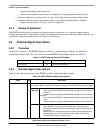
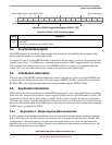
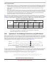
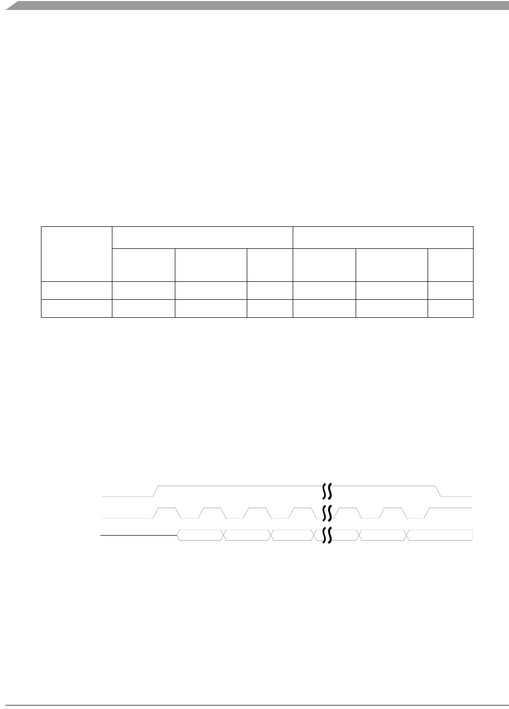
9.6.2 Application 2: 16-bit Message Transmission using SPI Protocol
In this second example, a 16-bit message is transmitted using three programmable output pins. The output
pins include a serial clock, an active-high chip select, and the serial data bit. The software is configured to
sample the serial data bit at the rising-edge of the clock with the data sent in a most-significant to
least-significant bit order. The resulting 3-bit output is shown in Figure 9-10.
Figure 9-10. GPIO SPI Example Timing Diagram
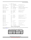
For this example, the processing of the SPI message is considerably more complex than the generation of
a simple square wave of the previous example. The code snippet used to extract the data bit from the
message and build the required GPIO data register writes is shown in Figure 9-11.
# subtest: send a 16-bit message via a SPI interface using a RGPIO
# the SPI protocol uses a 3-bit value: clock, chip-select, data
# the data is centered around the rising-edge of the clock
Table 9-11. Square-Wave Output Performance
Loop
Peripheral Bus-mapped GPIO RGPIO
Sq-Wave
Frequency
Frequency @
CPU f = 50 MHz
Relative
Speed
Sq-Wave
Frequency
Frequency @
CPU f = 50 MHz
Relative
Speed
bchg (1/24) × f MHz 2.083 MHz 1.00x (1/14) × f MHz 3.571 MHz 1.71x
set+clr (+toggle) (1/12) × f MHz 4.167 MHz 2.00x (1/8) × f MHz 6.250 MHz 3.00x
15
14 13 2
1
0
gpio_cs
gpio_clk
gpio_data