


Chapter 18 Version 1 ColdFire Debug (CF1_DEBUG)
MCF51QE128 MCU Series Reference Manual, Rev. 3
Freescale Semiconductor 367
Get the latest version from freescale.com
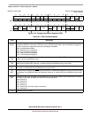
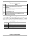
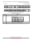
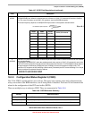
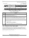
18.3.3 Configuration/Status Register 2 (CSR2)
The 32-bit CSR2 is partitioned into two sections. The upper byte contains status and configuration bits
always accessible to the BDM interface, even if debug mode is disabled. The lower 24 bits contain fields
related to the configuration of the PST trace buffer (PSTB).
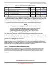
There are multiple ways to reference CSR2. They are summarized in Table 18-8.
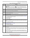
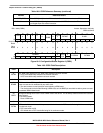
2–1
APCSC
Automatic PC synchronization control. Determines the periodic interval of PC address captures, if
XCSR[APCENB] is set. When the selected interval is reached, a SYNC_PC command is sent to the ColdFire
CPU. For more information on the SYNC_PC operation, see the APCENB description.
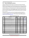
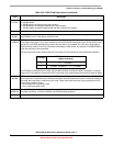
The chosen frequency depends on CSR2[APCDIV16] as shown in the equation and table below:
Eqn. 18-1
0
APCENB
Automatic PC synchronization enable. Enables the periodic output of the PC which can be used for PST/DDATA
trace synchronization.
As described in XCSR[APCSC], when the enabled periodic timer expires, a SYNC_PC command is sent to the
ColdFire CPU which generates a forced instruction fetch of the next instruction. The PST/DDATA module captures
the target address as defined by CSR[9] (two bytes if CSR[9] is cleared, three bytes if CSR[9] is set). This
produces a PST sequence of 0x5 (indicating a taken branch), followed by the PST marker indicating a 2- or 3-byte
address, and then the captured instruction address.
0 Automatic PC synchronization disabled
1 Automatic PC synchronization enabled
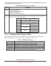
Table 18-8. CSR2 Reference Summary
Method Reference Details
READ_CSR2_BYTE Reads CSR2[31
–24] from the BDM interface. Available in all modes.
WRITE_CSR2_BYTE Writes CSR2[31–24] from the BDM interface. Available in all modes.
READ_DREG Reads CSR2[31–0] from the BDM interface. Classified as a non-intrusive BDM command.
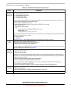
Table 18-7. XCSR Field Descriptions (continued)
Field Description
PC address capture period
2
APCSC 1+()
1024×
16
APCDIV16
----------------------------------------------------------=
XCSR
[APCENB]
CSR2
[APCDIV16]
XCSR
[APCSC]
SYNC_PC Interval
1 0 00 2048 cycles
1 0 01 4096 cycles
1 0 10 8192 cycles
1 0 11 16384 cycles
1 1 00 128 cycles
1 1 01 256 cycles
1 1 10 512 cycles
1 1 11 1024 cycles