


MCF51QE128 MCU Series Reference Manual, Rev. 3
188 Freescale Semiconductor
Get the latest version from freescale.com
Chapter 8 Interrupt Controller (CF1_INTC)
special case. The edge-sensitive nature of these requests means the encoded 3-bit level input from the
CF1_INTC to the V1 ColdFire core must change state before the CPU detects an interrupt. A
non-maskable interrupt (NMI) is generated each time the encoded interrupt level changes to level seven
(regardless of the SR[I] field) and each time the SR[I] mask changes from seven to a lower value while the
encoded request level remains at seven.
8.5 Initialization Information
The reset state of the CF1_INTC module enables the default IRQ mappings and clears any software-forced
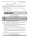
interrupt requests (INTC_FRC is cleared). The wake-up control register (INTC_WCR) is also disabled, so
it must be written before the processor executes any stop instructions to properly exit from any wait or stop
mode. Immediately after reset, the CF1_INTC begins its cycle-by-cycle evaluation of any asserted
interrupt requests and forms the appropriate encoded interrupt level and vector information for the V1
processor core.
8.6 Application Information
This section discusses three application topics: emulation of the HCS08’s one level interrupt nesting
structure, elevating the priority of two IRQs, and more details on the operation of the software interrupt
acknowledge (SWIACK) mechanism.
8.6.1 Emulation of the HCS08’s 1-Level IRQ Handling
As noted in Table 8-1, the HCS08 architecture specifies a 1-level IRQ nesting capability. Interrupt masking
is controlled by CCR[I], the interrupt mask flag: clearing CCR[I] enables interrupts, while setting CCR[I]
disables interrupts. The ColdFire architecture defines seven interrupt levels, controlled by the 3-bit
interrupt priority mask field in the status register, SR[I], and the hardware automatically supports nesting
of interrupts.
To emulate the HCS08’s 1-level IRQ capabilities on V1 ColdFire, only two SR[I] settings are used:
• Writing 0 to SR[I] enables interrupts.
• Writing 7 to SR[I] disables interrupts.
ColdFire treats the two level seven requests (IRQ pin and Low voltage detect) as non-maskable,
edge-sensitive interrupts.
ColdFire processors inhibit interrupt sampling during the first instruction of all exception handlers. This
allows any handler to effectively disable interrupts, if necessary, by raising the interrupt mask level
contained in the status register as the first instruction in the ISR. In addition, the V1 instruction set
architecture (ISA_C) includes an instruction (STLDSR) that stores the current interrupt mask level and
loads a value into the SR. This instruction is specifically intended for use as the first instruction of an
interrupt service routine which services multiple interrupt requests with different interrupt levels. For more
details see the ColdFire Family Programmer’s Reference Manual. A MOVE-to-SR instruction also
performs a similar function.