


MCF51QE128 MCU Series Reference Manual, Rev. 3
2-270 Freescale Semiconductor
13.4 Functional Description
This section provides a complete functional description of the IIC module.
13.4.1 IIC Protocol
The IIC bus system uses a serial data line (SDA) and a serial clock line (SCL) for data transfer. All devices
connected to it must have open drain or open collector outputs. A logic AND function is exercised on both
lines with external pull-up resistors. The value of these resistors is system dependent.
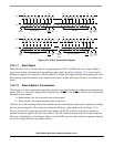
Normally, a standard communication is composed of four parts:
• Start signal
• Slave address transmission
• Data transfer
• Stop signal
The stop signal should not be confused with the CPU stop instruction. The IIC bus system communication
is described briefly in the following sections and illustrated in Figure 13-9.
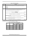
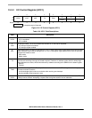
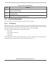
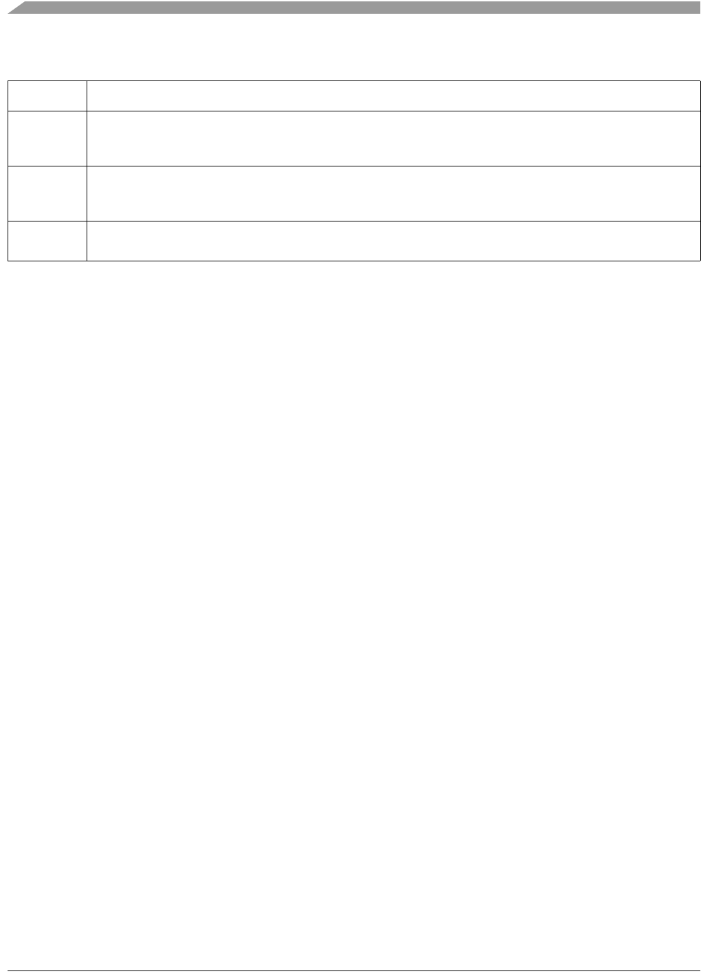
Table 13-9. IICC2 Field Descriptions
Field Description
7
GCAEN
General Call Address Enable. The GCAEN bit enables or disables general call address.
0 General call address is disabled
1 General call address is enabled
6
ADEXT
Address Extension. The ADEXT bit controls the number of bits used for the slave address.
0 7-bit address scheme
1 10-bit address scheme
2–0
AD[10:8]
Slave Address. The AD[10:8] field contains the upper three bits of the slave address in the 10-bit address
scheme. This field is only valid when the ADEXT bit is set.