


Chapter 18 Version 1 ColdFire Debug (CF1_DEBUG)
MCF51QE128 MCU Series Reference Manual, Rev. 3
380 Freescale Semiconductor
Get the latest version from freescale.com
18.3.11 Resulting Set of Possible Trigger Combinations
The resulting set of possible breakpoint trigger combinations consists of the following options where ||
denotes logical OR, && denotes logical AND, and {} denotes an optional additional trigger term:
One-level triggers of the form:
if (PC_breakpoint)
if (PC_breakpoint || Address_breakpoint{&& Data_breakpoint})
if (Address_breakpoint {&& Data_breakpoint})
Two-level triggers of the form:
if (PC_breakpoint)
then if (Address_breakpoint{&& Data_breakpoint})
if (Address_breakpoint {&& Data_breakpoint})
then if (PC_breakpoint)
In these examples, PC_breakpoint is the logical summation of the PBR0/PBMR, PBR1, PBR2, and PBR3
breakpoint registers; Address_breakpoint is a function of ABHR, ABLR, and AATR; Data_breakpoint is
a function of DBR and DBMR. In all cases, the data breakpoints can be included with an address
breakpoint to further qualify a trigger event as an option.
The breakpoint registers can also be used to define the start and stop recording conditions for the PST trace
buffer. For information on this functionality, see Section 18.3.3, “Configuration/Status Register 2
(CSR2)”.
18.4 Functional Description
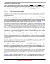
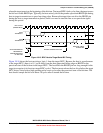
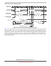
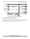
18.4.1 Background Debug Mode (BDM)
This section provides details on the background debug serial interface controller (BDC) and the BDM
command set.
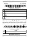
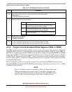
Table 18-22. Access Size and Operand Data Location
Address[1–0] Access Size Operand Location
00 Byte D[31
–24]
01 Byte D[23–16]
10 Byte D[15–8]
11 Byte D[7–0]
0x Word D[31–16]
1x Word D[15–0]
xx Longword D[31–0]