


MCF51QE128 MCU Series Reference Manual, Rev. 3
Freescale Semiconductor 51
Get the latest version from freescale.com
NOTE
If neither the WAITE nor STOPE bit is set when the CPU executes a STOP
instruction, the MCU does not enter either of the stop modes. Instead, the
MCU initiates an illegal opcode reset if CPUCR[IRD] is cleared or an
illegal instruction exception if CPUCR[IRD] is set.
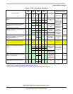
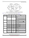
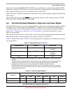
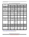
The stop modes are selected by setting the appropriate bits in the system power management status and
control 2 (SPMSC2) register. Table 3-1 shows all of the control bits that affect mode selection under
various conditions. The selected mode is entered following the execution of a STOP instruction.
Most background commands are not available in stop mode. The memory-access-with-status commands
do not allow memory access, but they report an error indicating that the MCU is in either stop or wait
mode. The BACKGROUND command can be used to wake the MCU from stop4 and enter halt mode if
the ENBDM bit was set prior to entering stop. After entering halt mode, all background commands are
available.
3.8.1 Stop2 Mode
Stop2 mode is entered by executing a STOP instruction under the conditions as shown in Table 3-1.
Most of the internal circuitry of the MCU is powered off in stop2 with the exception of the RAM and
optionally the RTC. Upon entering stop2, all I/O pin control signals are latched so that the pins retain their
states during stop2.
Exit from stop2 is performed by driving the wake-up pin (PTA5/IRQ/TPM1CLK/RESET) on the MCU to
zero.
NOTE
PTA5/IRQ/TPM1CLK/RESET
functions as an active-low wakeup input
when the MCU is in stop2, as long as the pin is configured as an input before
entering stop2. The pullup on this pin is not automatically enabled in stop2.
To enable the internal pullup, set PTAPE[PTAPE5].
In addition, the real-time counter (RTC) can wake the MCU from stop2, if enabled.
Upon wake-up from stop2 mode, the MCU starts up as from a power-on reset (POR):
• All module control and status registers are reset, with the exception of the power management
controller (SPMSC1/2/3), RTC, and debug trace buffer. Refer to the individual module chapters for
more information on which other registers are unaffected by wake-up from stop2 mode.
• The LVD reset function is enabled and the MCU remains in the reset state if V
DD
is below the LVD
trip point (low trip point selected due to POR).
• The CPU initiates reset exception processing by fetching the vectors at 0x(00)00_0000 and
0x(00)00_0004.