


MCF51QE128 MCU Series Reference Manual, Rev. 3
Freescale Semiconductor 43
Get the latest version from freescale.com
Chapter 3
Modes of Operation
3.1 Introduction
The operating modes of the MCF51QE128/64/32 are described in this chapter. Entry into each mode, exit
from each mode, and functionality while in each of the modes are described.
The overall system mode is generally a function of a number of separate, but inter-related variables: debug
mode, security mode, power mode, and clock mode. Clock modes were discussed in Section 1.4.3, “ICS
Modes of Operation”. This chapter explores the other dimensions of the system operating mode.
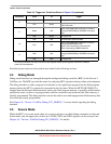
3.2 Features
• Debug mode for code development. For V1 ColdFire devices, such as MCF51QE128/64/32 ,
debug mode is mutually exclusive with use of secure mode (next item).
• Secure mode — BDC access to CPU resources is extremely restricted. It is possible to tell that the
device has been secured, and to clear security, which involves mass erasing the on-chip flash
memory. No other CPU access is allowed. Secure mode can be used in conjunction with each of
the power modes below.
• Run mode — CPU clocks can be run at full speed and the internal supply is fully regulated.
• LPrun mode — CPU and peripheral clocks are restricted to 250 kHz CPU clock and 125 kHz bus
clock maximum and the internal supply is in soft regulation.
• Wait mode — CPU shuts down to conserve power; peripheral clocks are running and full
regulation is maintained.
• LPwait mode — CPU shuts down to conserve power; peripheral clocks are running at reduced
speed (125 kHz maximum) and the internal voltage regulator is running in loose regulation mode.
• Stop modes — System (CPU and peripheral) clocks are stopped.
— Stop4 — All internal circuits are powered (full regulation mode) and internal clock sources still
at max frequency for fastest recovery.
— Stop3 — All internal circuits are loosely regulated and clocks sources are at minimal values
(125 kHz maximum), providing a good compromise between power utilization and speed of
recovery.
— Stop2 — Partial power-down of internal circuits; RAM content is retained. The lowest power
mode for this device. A reset is required to return from stop2 mode.
On the MCF51QE128/64/32 , wait, stop2, stop3, and stop4 are all entered via the CPU STOP instruction.
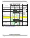
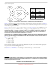
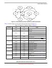
See Table 3-1, Figure 3-2, and subsequent sections of this chapter for details.