


Analog-to-Digital Converter (S08ADC12V1)
MCF51QE128 MCU Series Reference Manual, Rev. 3
222 Freescale Semiconductor
Get the latest version from freescale.com
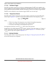
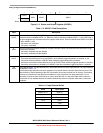
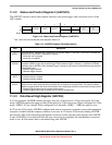
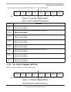
7654 3 210
RCOCO
AIEN ADCO ADCH
W
Reset:0001 1 111
Figure 11-3. Status and Control Register (ADCSC1)
Table 11-3. ADCSC1 Field Descriptions
Field Description
7
COCO
Conversion Complete Flag. The COCO flag is a read-only bit set each time a conversion is completed when the
compare function is disabled (ACFE = 0). When the compare function is enabled (ACFE = 1), the COCO flag is
set upon completion of a conversion only if the compare result is true. This bit is cleared when ADCSC1 is written
or when ADCRL is read.
0 Conversion not completed
1 Conversion completed
6
AIEN
Interrupt Enable AIEN enables conversion complete interrupts. When COCO becomes set while AIEN is high,
an interrupt is asserted.
0 Conversion complete interrupt disabled
1 Conversion complete interrupt enabled
5
ADCO
Continuous Conversion Enable. ADCO enables continuous conversions.
0 One conversion following a write to the ADCSC1 when software triggered operation is selected, or one
conversion following assertion of ADHWT when hardware triggered operation is selected.
1 Continuous conversions initiated following a write to ADCSC1 when software triggered operation is selected.
Continuous conversions are initiated by an ADHWT event when hardware triggered operation is selected.
4:0
ADCH
Input Channel Select. The ADCH bits form a 5-bit field that selects one of the input channels. The input channels
are detailed in Table 11-4.
The successive approximation converter subsystem is turned off when the channel select bits are all set. This
feature allows for explicit disabling of the ADC and isolation of the input channel from all sources. Terminating
continuous conversions this way prevents an additional, single conversion from being performed. It is not
necessary to set the channel select bits to all ones to place the ADC in a low-power state when continuous
conversions are not enabled because the module automatically enters a low-power state when a conversion
completes.
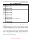
Table 11-4. Input Channel Select
ADCH Input Select
00000–01111 AD0–15
10000–11011 AD16–27
11100 Reserved
11101
V
REFH
11110 V
REFL
11111 Module disabled