


Chapter 18 Version 1 ColdFire Debug (CF1_DEBUG)
MCF51QE128 MCU Series Reference Manual, Rev. 3
Freescale Semiconductor 385
Get the latest version from freescale.com
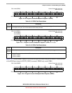
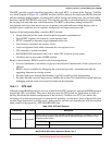
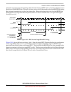
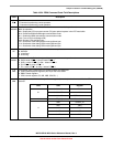
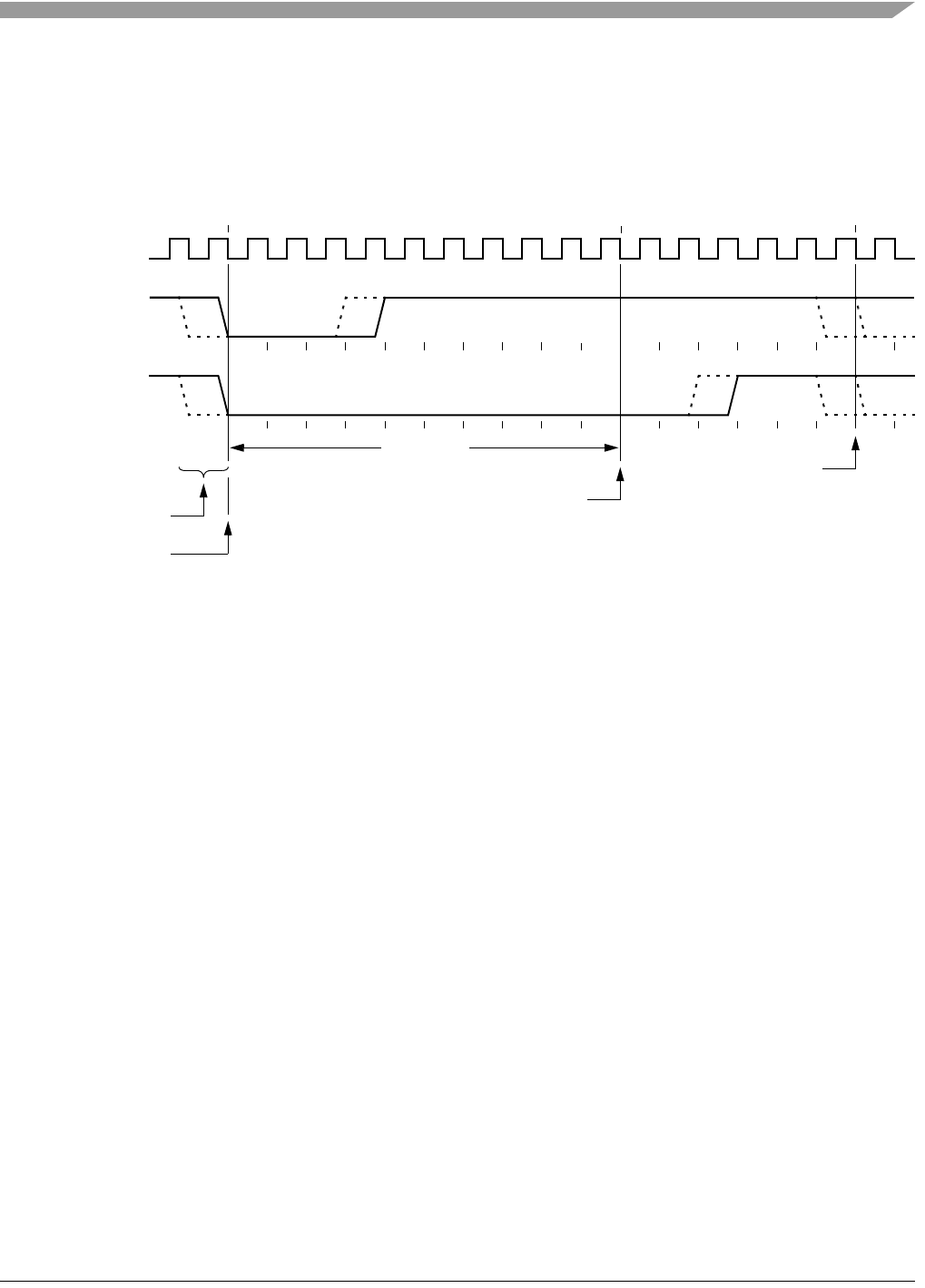
where the target perceives the beginning of the bit time. Ten target BDC clock cycles later, the target senses
the bit level on the BKGD pin. Typically, the host actively drives the pseudo-open-drain BKGD pin during
host-to-target transmissions to speed up rising edges. Because the target does not drive the BKGD pin
during the host-to-target transmission period, there is no need to treat the line as an open-drain signal
during this period.
Figure 18-15. BDC Host-to-Target Serial Bit Timing
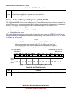
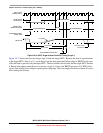
Figure 18-16 shows the host receiving a logic 1 from the target MCU. Because the host is asynchronous
to the target MCU, there is a 0–1 cycle delay from the host-generated falling edge on BKGD to the
perceived start of the bit time in the target MCU. The host holds the BKGD pin low long enough for the
target to recognize it (at least two target BDC cycles). The host must release the low drive before the target
MCU drives a brief active-high speedup pulse seven cycles after the perceived start of the bit time. The
host should sample the bit level about 10 cycles after it started the bit time.
EARLIEST START
TARGET SENSES BIT LEVEL
10 CYCLES
SYNCHRONIZATION
UNCERTAINTY
BDC CLOCK
(TARGET MCU)
HOST
TRANSMIT 1
HOST
TRANSMIT 0
PERCEIVED START
OF BIT TIME
OF NEXT BIT