


MCF51QE128 MCU Series Reference Manual, Rev. 3
Freescale Semiconductor 2-267
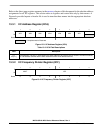
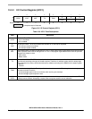
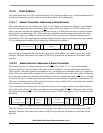
13.3.3 IIC Control Register (IICC1)
76543210
R
IICEN IICIE MST TX TXAK
000
W RSTA
Reset00000000
= Unimplemented or Reserved
Figure 13-5. IIC Control Register (IICC1)
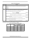
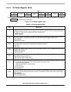
Table 13-6. IICC1 Field Descriptions
Field Description
7
IICEN
IIC Enable. The IICEN bit determines whether the IIC module is enabled.
0 IIC is not enabled
1 IIC is enabled
6
IICIE
IIC Interrupt Enable. The IICIE bit determines whether an IIC interrupt is requested.
0 IIC interrupt request not enabled
1 IIC interrupt request enabled
5
MST
Master Mode Select. The MST bit changes from a 0 to a 1 when a start signal is generated on the bus and master
mode is selected. When this bit changes from a 1 to a 0 a stop signal is generated and the mode of operation
changes from master to slave.
0Slave mode
1 Master mode
4
TX
Transmit Mode Select. The TX bit selects the direction of master and slave transfers. In master mode, this bit
should be set according to the type of transfer required. Therefore, for address cycles, this bit is always high.
When addressed as a slave, this bit should be set by software according to the SRW bit in the status register.
0 Receive
1 Transmit
3
TXAK
Transmit Acknowledge Enable. This bit specifies the value driven onto the SDA during data acknowledge cycles
for master and slave receivers.
0 An acknowledge signal is sent out to the bus after receiving one data byte
1 No acknowledge signal response is sent
2
RSTA
Repeat start. Writing a 1 to this bit generates a repeated start condition provided it is the current master. This bit
is always read as cleared. Attempting a repeat at the wrong time results in loss of arbitration.