


Analog Comparator (S08ACMPVLPV1)
MCF51QE128 MCU Series Reference Manual, Rev. 3
Freescale Semiconductor 213
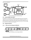
10.4 Functional Description
The ACMP module can be used to compare:
• Two analog input voltages applied to ACMP0 and ACMP1 or
• An analog input voltage applied to ACMP0 with an internal bandgap reference voltage
The ACBGS bit selects the mode of operation. The comparator output is high when the non-inverting input
is greater than the inverting input, and low when the non-inverting input is less than the inverting input.
The ACMOD0 and ACMOD1 bits select the condition that cause the ACF bit to be set. The ACF bit can
be set on a rising edge of the comparator output, a falling edge of the comparator output, or either a rising
or a falling edge (toggle). The comparator output can be read directly through the ACO bit.
10.5 Interrupts
The ACMP module is capable of generating an interrupt on a compare event. The interrupt request is
asserted when both the ACIE bit and the ACF bit are set. The interrupt is deasserted by clearing either the
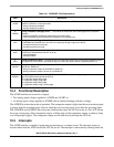
Table 10-1. ACMPxSC Field Descriptions
Field Description
7
ACME
Analog Comparator Module Enable — The ACME bit enables the ACMP module. When the module is not
enabled, it remains in a low power state.
0 Analog Comparator disabled.
1 Analog Comparator enabled.
6
ACBGS
Analog Comparator Bandgap Select — The ACBGS bit selects the internal bandgap as the comparator
reference.
0 External pin ACMP1 selected as comparator non-inverting input.
1 Internal bandgap reference selected as comparator non-inverting input.
5
ACF
Analog Comparator Flag — The ACF bit is set when a compare event occurs. Compare events are defined by
the ACMOD0 and ACMOD1 bits. The ACF bit is cleared by writing a logic one to the bit.
0 Compare event has not occurred.
1 Compare event has occurred.
4
ACIE
Analog Comparator Interrupt Enable — The ACIE bit enables the interrupt from the ACM. When this bit is set,
an interrupt is asserted when the ACF bit is set.
0 Interrupt disabled.
1 Interrupt enabled.
3
ACO
Analog Comparator Output — Reading the ACO bit returns the current value of the analog comparator output.
The register bit is reset to zero and reads as logic zero when the ACMP module is disabled (ACME = 0).
2
ACOPE
Analog Comparator Output Pin Enable — ACOPE enables the comparator output to be placed onto the
external pin, ACMPx1O.
0 Analog comparator output not available on ACMPx1O.
1 Analog comparator output is driven out on ACMPx1O.
1:0
ACMOD
Analog Comparator Modes — The ACMOD1 and ACMOD0 bits select the flag setting mode that controls the
type of compare event that sets the ACF bit.
00 Comparator output falling edge.
01 Comparator output rising edge.
10 Comparator output falling edge.
11 Comparator output rising or falling edge.