


MCF51QE128 MCU Series Reference Manual, Rev. 3
96 Freescale Semiconductor
Get the latest version from freescale.com
Chapter 5 Resets, Interrupts, and General System Control
NOTE
This pin does not contain a clamp diode to V
DD
and should not be driven
above V
DD
.
NOTE
The voltage measured on the internally pulled up RESET pin is not pulled
to V
DD
. The internal gates connected to this pin are pulled to V
DD
. The
RESET pullup should not be used to pull up components external to the
MCU.
5.4.1.2 Edge and Level Sensitivity
The IRQMOD control bit reconfigures the detection logic so it detects edge events and pin levels. In the
edge and level detection mode, the IRQF status flag becomes set when an edge is detected (when the IRQ
pin changes from the deasserted to the asserted level), but the flag is continuously set (and cannot be
cleared) as long as the IRQ pin remains at the asserted level.
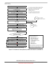
5.4.1.3 External Interrupt Initialization
When the IRQ pin is first enabled, it is possible to get a false interrupt flag. To prevent a false interrupt
request during IRQ initialization, the user should do the following:
1. Mask interrupts by clearing IRQSC[IRQIE].
2. Select the pin polarity by setting the appropriate IRQSC[IRQEDG] bits.
3. If using internal pull-up/pull-down device, clear IRQSC[IRQPDD].
4. Enable the IRQ pin by setting IRQSC[IRQPE].
5. Write to IRQSC[IRQACK] to clear any false interrupts.
6. Set IRQSC[IRQIE] to enable interrupts.
5.5 Low-Voltage Detect (LVD) System
The MCF51QE128/64/32 includes a system to guard against low voltage conditions to protect memory
contents and control MCU system states during supply voltage variations. The system is comprised of a
power-on reset (POR) circuit and a LVD circuit with a user-selectable trip voltage, high (V
LVDH
) or low
(V
LVDL
). The LVD circuit is enabled when the SPMSC1[LVDE] bit is set and the trip voltage is selected
by the SPMSC3[LVDV] bit. The LVD is disabled upon entering stop2 or stop3 modes unless the LVDSE
bit is set. If LVDE and LVDSE are set when the STOP instruction is processed, the device enters stop4
mode. The LVD can be left enabled in this mode.
5.5.1 Power-On Reset Operation
When power is initially applied to the MCU or the supply voltage drops below the power-on reset re-arm
voltage level, V
POR
, the POR circuit causes a reset condition. As the supply voltage rises, the LVD circuit
holds the MCU in reset until the supply has risen above the LVD low threshold, V
LVDL
. The
SRS[POR,LVD] bits are set following a POR.