


MCF51QE128 MCU Series Reference Manual, Rev. 3
116 Freescale Semiconductor
Get the latest version from freescale.com
Chapter 6 Parallel Input/Output Control
The set/clear/toggle functionality allows software to affect an individual bit with a single write instruction,
rather than using a read-modify-write sequence.
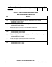
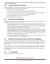
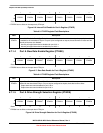
6.3.1 Port Data Set Registers
The port data set registers (PTxSET) are write-only registers associated with ports C and E. Writing to
these registers has the result: PortData = PortData || SetPattern. A subsequent port data register (PTxD)
read reflects the changed result.
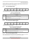
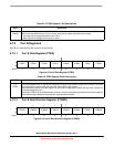
6.3.2 Port Data Clear Registers
The port data clear registers (PTxCLR) are write-only registers associated with ports C and E. Writing to
these registers has the result: PortData = PortData && ~ClearPattern. A subsequent port data register
(PTxD) read reflects the changed result.
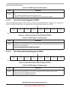
6.3.3 Port Data Toggle Register
The port data toggle registers (PTxTOG) are write-only registers associated with ports C & E. Writing to
these registers has the result: PortData = PortData ^ TogglePattern. A subsequent port data register (PTxD)
read reflects the changed result.
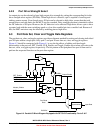
6.4 V1 ColdFire Rapid GPIO Functionality
The set/clear/toggle functionality descibed in Section 6.3, “Port Data Set, Clear and Toggle Data
Registers,” resides on the device peripheral bus. The V1 ColdFire core is capable of performing higher
speed I/O via its local bus, which does not have latency penalties associated with the on-chip peripheral
bus bridge. The Rapid GPIO module contains data, direction, and enable registers along with set, clear,
and toggle registers, which are based at address 0x(00)C0_0000. This functionality can be programmed to
take priority on ports C and E.
This functionality is further defined in Chapter 9, “Rapid GPIO (RGPIO)”.
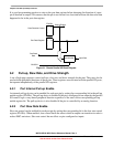
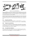
6.5 Keyboard Interrupts
Some port A, some port B, and all port D pins can be configured as keyboard interrupt inputs and as an
external means of waking the MCU from stop or wait low-power modes. The block diagram for each
keyboard interrupt logic is shown Figure 6-3.