


ColdFire Core
MCF51QE128 MCU Series Reference Manual, Rev. 3
156 Freescale Semiconductor
All ColdFire processors inhibit interrupt sampling during the first instruction of all exception handlers.
This allows any handler to disable interrupts effectively, if necessary, by raising the interrupt mask level
contained in the status register. In addition, the ISA_C architecture includes an instruction (STLDSR) that
stores the current interrupt mask level and loads a value into the SR. This instruction is specifically
intended for use as the first instruction of an interrupt service routine that services multiple interrupt
requests with different interrupt levels. Finally, the V1 ColdFire core includes the CPUCR[IME] bit that
forces the processor to automatically raise the mask level to 7 during the interrupt exception, removing the
need for any explicit instruction in the service routine to perform this function. For more details, see
ColdFire Family Programmer’s Reference Manual.
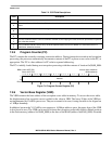
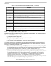
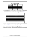
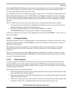
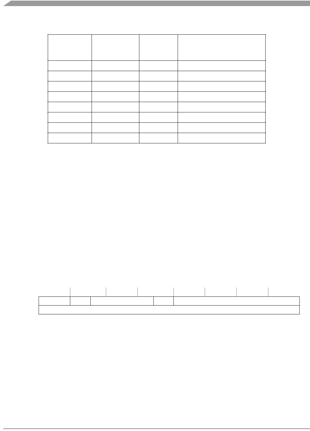
7.3.2.1 Exception Stack Frame Definition
Figure 7-10 shows exception stack frame. The first longword contains the 16-bit format/vector word (F/V)
and the 16-bit status register, and the second longword contains the 32-bit program counter address.
The 16-bit format/vector word contains three unique fields:
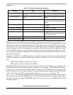
• A 4-bit format field at the top of the system stack is always written with a value of 4, 5, 6, or 7 by
the processor, indicating a two-longword frame format. See Table 7-7.
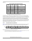
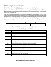
25–31 0x064–0x07C — Reserved
32–47 0x080–0x0BC Next Trap # 0-15 instructions
48–60 0x0C0–0x0F0 — Reserved
61 0x0F4 Fault Unsupported instruction
62–63 0x0F8–0x0FC — Reserved
64–95 0x100–0x17C Next Device-specific interrupts
96–102 0x180–0x198 Next Level 1–7 software interrupts
103–255 0x19C–0x3FC — Reserved, unused for V1
1
Fault refers to the PC of the instruction that caused the exception. Next refers to the PC
of the instruction that follows the instruction that caused the fault.
313029282726252423222120191817161514131211109876543210
SSP → Format FS[3:2] Vector FS[1:0] Status Register
+ 0x4
Program Counter
Figure 7-10. Exception Stack Frame Form
Table 7-6. Exception Vector Assignments (continued)
Vector
Number(s)
Vector
Offset (Hex)
Stacked
Program
Counter
Assignment