


MCF51QE128 MCU Series Reference Manual, Rev. 3
94 Freescale Semiconductor
Get the latest version from freescale.com
Chapter 5 Resets, Interrupts, and General System Control
5.3.1 Computer Operating Properly (COP) Watchdog
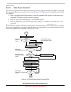
The COP watchdog forces a system reset when the application software fails to execute as expected. To
prevent a system reset from the COP timer (when it is enabled), application software must reset the COP
counter periodically. If the application program gets lost and fails to reset the COP counter before it times
out, a system reset is generated to force the system back to a known starting point.
After any reset, the SOPT1[COPE] bit is set enabling the COP watchdog (see Section 5.7.3, “System
Options Register 1 (SOPT1),” for additional information). If the COP watchdog is not used in an
application, it can be disabled by clearing COPE. The COP counter is reset by writing any value to the
address of SRS. This write does not affect the data in the read-only SRS. Instead, the act of writing to this
address is decoded and sends a reset signal to the COP counter.
The SOPT2[COPCLKS] bit selects the clock source used for the COP timer (see Section 5.7.4, “System
Options Register 2 (SOPT2),” for additional information). The clock source options are either the bus
clock or an internal 1-kHz clock source. With each clock source, there is an associated short and long
time-out controlled by the SOPT1[COPT] bit. Table 5-1 summaries the control functions of the COPCLKS
and COPT bits. The COP watchdog defaults to operation from the 1-kHz clock source and the associated
long time-out (2
8
cycles).
Write to the write-once SOPT1
1
and SOPT2 registers during reset initialization to lock in the settings, even
if the application uses the default reset settings of COPE, COPCLKS, and COPT. That way, they cannot
be changed accidentally if the application program gets lost. The initial writes to SOPT1 and SOPT2 reset
the COP counter.
The write to SRS that services (clears) the COP counter must not be placed in an interrupt service routine
(ISR) because the ISR could continue to be executed periodically even if the main application program
fails.
In the CPU halt state, the COP counter does not increment.
When the bus clock source is selected, the COP counter does not increment while the system is in stop
mode. The COP counter resumes as soon as the MCU exits stop mode.
When the 1-kHz clock source is selected, the COP counter is re-initialized to zero upon entry to stop mode.
The COP counter begins from zero after the MCU exits stop mode.
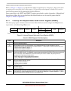
Table 5-1. COP Configuration Options
Control Bits
Clock Source COP Overflow Count
COPCLKS COPT
00~1 kHz2
5
cycles (32 ms)
1
1
Values are shown in this column based on t
LPO
=1ms.
01~1 kHz2
8
cycles (256 ms)
1
10Bus 2
13
cycles
11Bus 2
18
cycles
1. The SOPT1[WAITE] bit can be written multiple times. Other bits are write-once.