


Chapter 18 Version 1 ColdFire Debug (CF1_DEBUG)
MCF51QE128 MCU Series Reference Manual, Rev. 3
376 Freescale Semiconductor
Get the latest version from freescale.com
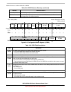
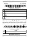
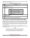
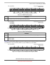
18.3.8 Program Counter Breakpoint/Mask Registers (PBR0–3, PBMR)
The PBRn registers define instruction addresses for use as part of the trigger. These registers’ contents are
compared with the processor’s program counter register when the appropriate valid bit is set (for PBR1–3)
and TDR is configured appropriately. PBR0 bits are masked by setting corresponding PBMR bits (PBMR
has no effect on PBR1–3). Results are compared with the processor’s program counter register, as defined
in TDR. The PC breakpoint registers, PBR1–3, have no masking associated with them, but do include a
valid bit. These registers’ contents are compared with the processor’s program counter register when TDR
is configured appropriately.
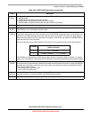
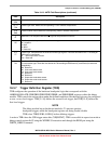
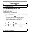
The PC breakpoint registers are accessible in supervisor mode using the WDEBUG instruction and
through the BDM port using the WRITE_DREG command using values shown in Section 18.4.1.4, “BDM
Command Set Descriptions”.
NOTE
Version 1 ColdFire core devices implement a 24-bit, 16-Mbyte address map.
When programming these registers with a 32-bit address, the upper byte
should be zero-filled when referencing the flash, RAM, and RGPIO regions,
and set to 0xFF when referencing any of the slave peripheral devices.
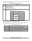
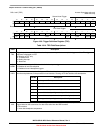
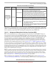
5
L1DI
Level 1 data breakpoint invert. Inverts the logical sense of all the data breakpoint comparators. This can develop a
trigger based on the occurrence of a data value other than the DBR contents.
0 No inversion
1 Invert data breakpoint comparators.
4–2
L1EA
Enable level 1 address breakpoint. Setting an L1EA bit enables the corresponding address breakpoint. Clearing all
three bits disables the address breakpoint.
1
L1EPC
Enable level 1 PC breakpoint.
0 Disable PC breakpoint
1 Enable PC breakpoint
0
L1PCI
Level 1 PC breakpoint invert.
0 The PC breakpoint is defined within the region defined by PBRn and PBMR.
1 The PC breakpoint is defined outside the region defined by PBRn and PBMR.
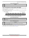
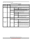
Table 18-14. TDR Field Descriptions (continued)
Field Description
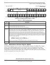
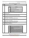
TDR Bit Description
4 Enable address breakpoint inverted. Breakpoint is based
outside the range between ABLR and ABHR.
3 Enable address breakpoint range. The breakpoint is based on
the inclusive range defined by ABLR and ABHR.
2 Enable address breakpoint low. The breakpoint is based on the
address in the ABLR.