


MCF51QE128 MCU Series Reference Manual, Rev. 3
106 Freescale Semiconductor
Get the latest version from freescale.com
Chapter 5 Resets, Interrupts, and General System Control
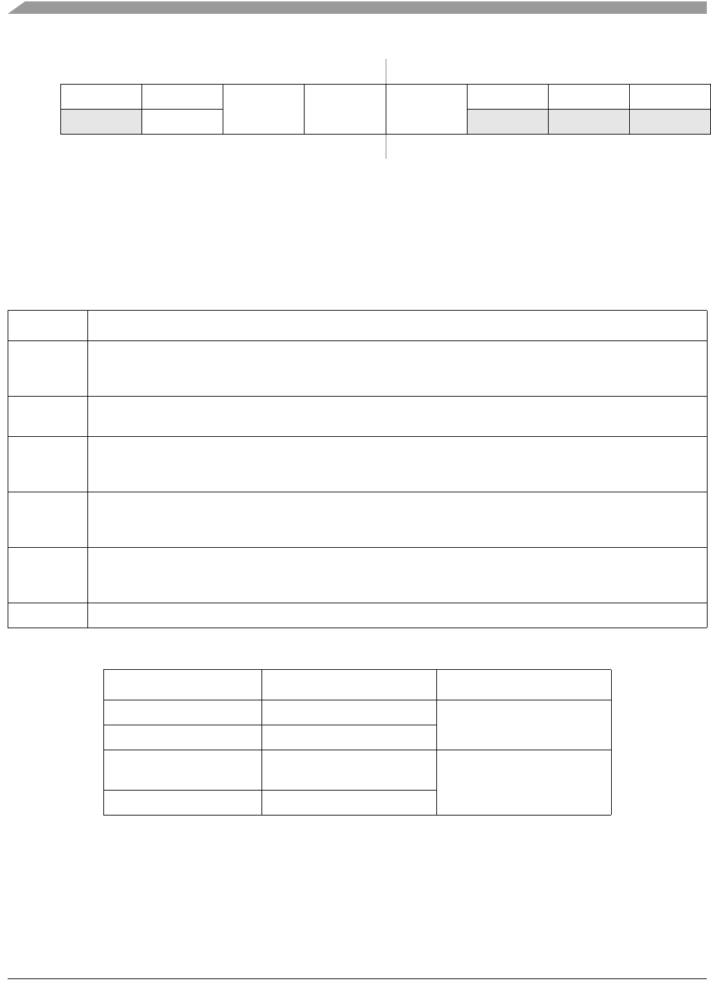
76543210
RLVWF 0
LVDV LVWV LVWIE
000
W LVWACK
POR:
0
1
0000000
LVR:
0
1
0UU0000
Any other
reset:
0
1
0UU0000
1
LVWF is set when V
Supply
transitions below the trip point or after reset and V
Supply
is already below V
LVW
.
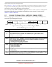
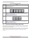
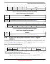
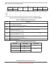
Figure 5-9. System Power Management Status and Control 3 Register (SPMSC3)
Table 5-10. SPMSC3 Register Field Descriptions
Field Description
7
LVWF
Low-Voltage Warning Flag. The LVWF bit indicates the low voltage warning status.
0 Low voltage warning not present.
1 Low voltage warning is present or was present.
6
LVWACK
Low-Voltage Warning Acknowledge. Writing a 1 to LVWACK clears LVWF if a low voltage warning is not present.
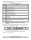
5
LVDV
Low-Voltage Detect Voltage Select. The LVDV bit selects the LVD trip point voltage (V
LVD
).
0 Low trip point selected (V
LVD
= V
LVDL
).
1 High trip point selected (V
LVD
= V
LVDH
).
4
LVWV
Low-Voltage Warning Voltage Select. The LVWV bit selects the LVW trip point voltage (V
LVW
).
0 Low trip point selected (V
LVW
= V
LVWL
).
1 High trip point selected (V
LVW
= V
LVWH
).
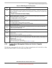
3
LVWIE
Low-Voltage Warning Interrupt Enable. This bit enables hardware interrupt requests for LVWF.
0 Hardware interrupt disabled (use polling).
1 Request a hardware interrupt when LVWF is set.
2–0 Reserved, should be cleared.
Table 5-11. LVD and LVW Trip Point Typical Values
1
1
See the MCF51QE128 Data Sheet for minimum and maximum values.
LVDV:LVWV LVW Trip Point LVD Trip Point
00 V
LVWL
= 2.15 V
LVDL
= 1.86
01 V
LVWL
= 2.48
10
Not Recommended
V
LVWL
= 2.15 V
LVDL
= 2.15
11 V
LVWL
= 2.48