


Analog-to-Digital Converter (S08ADC12V1)
MCF51QE128 MCU Series Reference Manual, Rev. 3
Freescale Semiconductor 233
Get the latest version from freescale.com
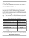
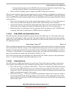
example, in 10-bit mode, with the bus clock selected as the input clock source, the input clock divide-by-1
ratio selected, and a bus frequency of 8 MHz, then the conversion time for a single conversion is:
NOTE
The ADCK frequency must be between f
ADCK
minimum and f
ADCK
maximum to meet ADC specifications.
11.4.5 Automatic Compare Function
The compare function can be configured to check for an upper or lower limit. After the input is sampled
and converted, the result is added to the two’s complement of the compare value (ADCCVH and
ADCCVL). When comparing to an upper limit (ACFGT = 1), if the result is greater-than or equal-to the
compare value, COCO is set. When comparing to a lower limit (ACFGT = 0), if the result is less than the
compare value, COCO is set. The value generated by the addition of the conversion result and the two’s
complement of the compare value is transferred to ADCRH and ADCRL.
Upon completion of a conversion while the compare function is enabled, if the compare condition is not
true, COCO is not set and no data is transferred to the result registers. An ADC interrupt is generated upon
the setting of COCO if the ADC interrupt is enabled (AIEN = 1).
NOTE
The compare function can monitor the voltage on a channel while the MCU
is in wait or stop3 mode. The ADC interrupt wakes the MCU when the
compare condition is met.
11.4.6 MCU Wait Mode Operation
Wait mode is a lower power-consumption standby mode from which recovery is fast because the clock
sources remain active. If a conversion is in progress when the MCU enters wait mode, it continues until
completion. Conversions can be initiated while the MCU is in wait mode by means of the hardware trigger
or if continuous conversions are enabled.
The bus clock, bus clock divided by two, and ADACK are available as conversion clock sources while in
wait mode. The use of ALTCLK as the conversion clock source in wait is dependent on the definition of
ALTCLK for this MCU. Consult the module introduction for information on ALTCLK specific to this
MCU.
A conversion complete event sets the COCO and generates an ADC interrupt to wake the MCU from wait
mode if the ADC interrupt is enabled (AIEN = 1).
23 ADCK Cyc
Conversion time =
8 MHz/1
Number of bus cycles = 3.5 ms x 8 MHz = 28 cycles
5 bus Cyc
8 MHz
+
= 3.5 ms