


MCF51QE128 MCU Series Reference Manual, Rev. 3
310 Freescale Semiconductor
Get the latest version from freescale.com
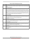
If RDRF was already set when a new character is ready to be transferred from the receive shifter to the
receive data buffer, the overrun (OR) flag is set instead of the data along with any associated NF, FE, or
PF condition is lost.
At any time, an active edge on the RxD serial data input pin causes the RXEDGIF flag to set. The
RXEDGIF flag is cleared by writing a 1 to it. This function does depend on the receiver being enabled
(RE = 1).
15.3.5 Additional SCI Functions
The following sections describe additional SCI functions.
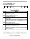
15.3.5.1 8- and 9-Bit Data Modes
The SCI system (transmitter and receiver) can be configured to operate in 9-bit data mode by setting the
M control bit in SCIxC1. In 9-bit mode, there is a ninth data bit to the left of the msb of the SCI data
register. For the transmit data buffer, this bit is stored in T8 in SCIxC3. For the receiver, the ninth bit is
held in R8 in SCIxC3.
For coherent writes to the transmit data buffer, write to the T8 bit before writing to SCIxD.
If the bit value to be transmitted as the ninth bit of a new character is the same as for the previous character,
it is not necessary to write to T8 again. When data is transferred from the transmit data buffer to the
transmit shifter, the value in T8 is copied at the same time data is transferred from SCIxD to the shifter.
The 9-bit data mode is typically used with parity to allow eight bits of data plus the parity in the ninth bit,
or it is used with address-mark wakeup so the ninth data bit can serve as the wakeup bit. In custom
protocols, the ninth bit can also serve as a software-controlled marker.
15.3.5.2 Stop Mode Operation
During all stop modes, clocks to the SCI module are halted.
In stop1 and stop2 modes, all SCI register data is lost and must be re-initialized upon recovery from these
two stop modes. No SCI module registers are affected in stop3 mode.
The receive input active edge detect circuit remains active in stop3 mode, but not in stop2. An active edge
on the receive input brings the CPU out of stop3 mode if the interrupt is not masked (RXEDGIE = 1).
Because the clocks are halted, the SCI module resumes operation upon exit from stop (only in stop3 mode).
Software should ensure stop mode is not entered while there is a character being transmitted out of or
received into the SCI module.
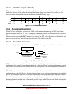
15.3.5.3 Loop Mode
When LOOPS is set, the RSRC bit in the same register chooses between loop mode (RSRC = 0) or
single-wire mode (RSRC = 1). Loop mode is sometimes used to check software, independent of
connections in the external system, to help isolate system problems. In this mode, the transmitter output is