


Timer/PWM Module (S08TPMV3)
MCF51QE128 MCU Series Reference Manual, Rev. 3
352 Freescale Semiconductor
Get the latest version from freescale.com
Input capture, output compare, and edge-aligned PWM functions do not make sense when the counter is
operating in up/down counting mode so this implies that all active channels within a TPM must be used in
CPWM mode when CPWMS is set.
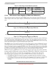
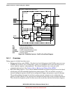
Because the TPM is connected to an 8-bit peripheral bus, the settings in the timer channel registers are
buffered to ensure coherent 16-bit updates and to avoid unexpected PWM pulse widths. Writes to
TPMxMODH, TPMxMODL, TPMxCnVH, and TPMxCnVL, actually write to buffer registers.
In center-aligned PWM mode, the TPMxCnVH:L registers are updated with the value of their write buffer
according to the value of CLKSB:CLKSA bits:
• If CLKSB and CLKSA are cleared, the registers are updated when the second byte is written
• If CLKSB and CLKSA are not cleared, the registers are updated after both bytes are written, and
the TPM counter changes from TPMxMODH:TPMxMODL − 1 to TPMxMODH:TPMxMODL. If
the TPM counter is a free-running counter, the update is made when the TPM counter changes from
0xFFFE to 0xFFFF.
When TPMxCNTH:TPMxCNTL equals TPMxMODH:TPMxMODL, the TPM optionally generates a
TOF interrupt at the end of this count.
Writing to TPMxSC cancels any values written to TPMxMODH and/or TPMxMODL and resets the
coherency mechanism for the modulo registers. Writing to TPMxCnSC cancels any values written to the
channel value registers and resets the coherency mechanism for TPMxCnVH:TPMxCnVL.
17.5 Reset Overview
17.5.1 General
The TPM is reset whenever any MCU reset occurs.
17.5.2 Description of Reset Operation
Reset clears TPMxSC, which disables clocks to the TPM and disables timer overflow interrupts
(TOIE = 0). CPWMS, MSnB, MSnA, ELSnB, and ELSnA are all cleared. This configures all TPM
channels for input-capture operation with the associated pins disconnected from I/O pin logic (all MCU
pins related to the TPM revert to general purpose I/O pins).
17.6 Interrupts
17.6.1 General
The TPM generates an optional interrupt for the main counter overflow and an interrupt for each channel.
The meaning of channel interrupts depends on each channel’s mode of operation. If the channel is
configured for input capture, the interrupt flag is set each time the selected input capture edge is
recognized. If the channel is configured for output compare or PWM modes, the interrupt flag is set each
time the main timer counter matches the value in the 16-bit channel value register.