


MCF51QE128 MCU Series Reference Manual, Rev. 3
Freescale Semiconductor 281
Get the latest version from freescale.com
Chapter 14
Real-Time Counter (S08RTCV1)
14.1 Introduction
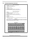
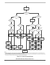
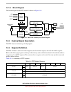
The real-time counter (RTC) consists of one 8-bit counter, one 8-bit comparator, several binary-based and
decimal-based prescaler dividers, three clock sources, and one programmable periodic interrupt. This
module can be used for time-of-day, calendar, or any task scheduling functions. It can also serve as a cyclic
wake up from low-power modes without the need of external components.
14.1.1 ADC Hardware Trigger
The RTC can be enabled as a hardware trigger for the ADC module by setting ADCSC2[ADTRG]. When
enabled, the ADC is triggered each time RTCINT matches RTCMOD. The RTC interrupt does not have to
be enabled to trigger the ADC.
14.1.2 RTC Clock Sources
The RTC module on MCF51QE128 Series can be clocked from ICSIRCLK, OSCOUT, or the LPO.
In this chapter, ERCLK is replaced by OSCOUT for this MCU.
14.1.3 RTC Modes of Operation
All clock sources are available in all modes except stop2. The OSCOUT and LPO can be enabled as the
clock source of the RTC in stop2.
14.1.3.1 RTC Status after Stop2 Wakeup
The registers associated with the RTC are unaffected after a stop2 wakeup.
14.1.3.2 Clocks in Stop Modes
In the MCF51QE128 Series, LPO and OSCOUT can be used in stop2 and stop3. IRCLK is available only
in stop3.
14.1.4 RTC Clock Gating
The bus clock to the RTC can be gated on and off with SCGC2[RTC]. This bit is set after any reset, which
enables the bus clock to this module. To conserve power, the RTC bit can be cleared to disable the clock
to this module when not in use. See Section 5.6, “Peripheral Clock Gating,” for details.