


Internal Clock Source (S08ICSV3)
MCF51QE128 MCU Series Reference Manual, Rev. 3
250 Freescale Semiconductor
Get the latest version from freescale.com
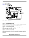
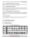
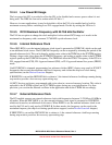
12.3.1 ICS Control Register 1 (ICSC1)
76543210
R
CLKS RDIV IREFS IRCLKEN IREFSTEN
W
Reset: 0 0 0 0 0 1 0 0
Figure 12-3. ICS Control Register 1 (ICSC1)
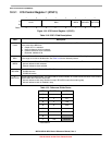
Table 12-2. ICSC1 Field Descriptions
Field Description
7:6
CLKS
Clock Source Select. Selects the clock source that controls the bus frequency. The actual bus frequency depends
on the value of the BDIV bits.
00 Output of FLL is selected.
01 Internal reference clock is selected.
10 External reference clock is selected.
11 Reserved, defaults to 00.
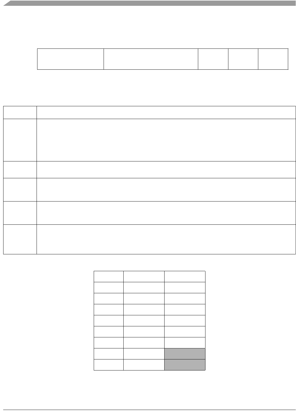
5:3
RDIV
Reference Divider. Selects the amount to divide down the external reference clock. Resulting frequency must be
in the range 31.25 kHz to 39.0625 kHz. See Table 12 -3 for the divide-by factors.
2
IREFS
Internal Reference Select. The IREFS bit selects the reference clock source for the FLL.
1 Internal reference clock selected
0 External reference clock selected
1
IRCLKEN
Internal Reference Clock Enable. The IRCLKEN bit enables the internal reference clock for use as ICSIRCLK.
1 ICSIRCLK active
0 ICSIRCLK inactive
0
IREFSTEN
Internal Reference Stop Enable. The IREFSTEN bit controls whether or not the internal reference clock remains
enabled when the ICS enters stop mode.
1 Internal reference clock stays enabled in stop if IRCLKEN is set before entering stop
0 Internal reference clock is disabled in stop
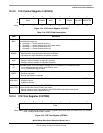
Table 12-3. Reference Divide Factor
RDIV RANGE=0 RANGE=1
0
1
1
1
Reset default
32
1
264
2
4 128
3
8 256
4
16 512
5
32 1024
6
64 Reserved
7
128 Reserved