


MCF51QE128 MCU Series Reference Manual, Rev. 3
114 Freescale Semiconductor
Get the latest version from freescale.com
Chapter 6 Parallel Input/Output Control
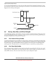
It is good programming practice to write to the port data register before changing the direction of a port
pin to become an output. This ensures that the pin is not driven for a short time with an old data value that
happened to be in the port data register.
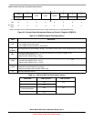
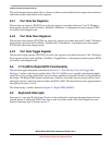
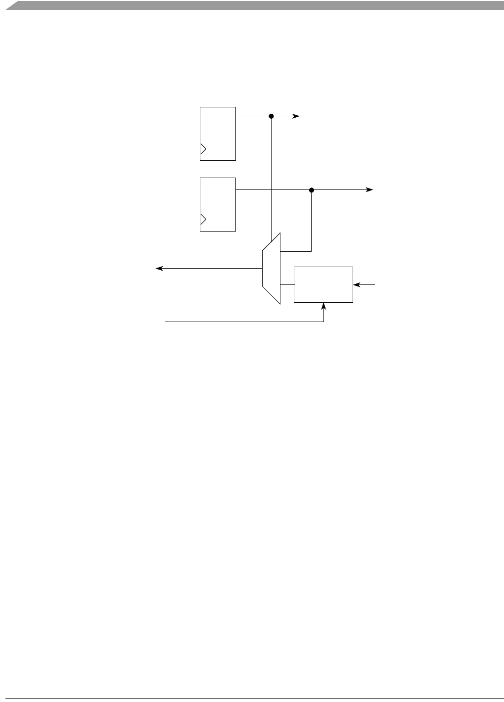
Figure 6-1. Classic Parallel I/O Block Diagram
6.2 Pull-up, Slew Rate, and Drive Strength
A set of high page registers control pull-ups, slew rate, and drive strength for the pins. They may also be
used with the peripheral functions on these pins. These registers are associated with the parallel I/O ports,
but operate independently of the parallel I/O registers.
6.2.1 Port Internal Pull-up Enable
An internal pull-up device can be enabled for each port pin by setting the corresponding bit in the pull-up
enable register (PTxPEn). The pull-up device is disabled if the pin is configured as an output by the parallel
I/O control logic or any shared peripheral function regardless of the state of the corresponding pull-up
enable register bit. The pull-up device is also disabled if the pin is controlled by an analog function.
6.2.2 Port Slew Rate Enable
Slew rate control can be enabled for each port pin by setting the corresponding bit in the slew rate control
register (PTxSEn). When enabled, slew control limits the rate at which an output can transition in order to
reduce EMC emissions. Slew rate control has no effect on pins configured as inputs.
QD
QD
1
0
Port Read
PTxDDn
PTxDn
Output Enable
Output Data
Input Data
Synchronizer
Data
BUSCLK
Port Data Register
Data Direction Control