


MCF51QE128 MCU Series Reference Manual, Rev. 3
Freescale Semiconductor 105
Get the latest version from freescale.com
Chapter 5 Resets, Interrupts, and General System Control
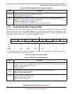
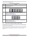
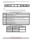
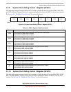
5.7.8 System Power Management Status and Control 3 Register
(SPMSC3)
This high page register reports the status of the low voltage warning function and to select the low voltage
detect trip voltage. SPMSC3 is not reset when exiting from stop2.
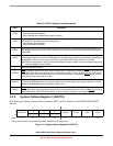
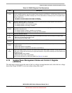
Table 5-9. SPMSC2 Register Field Descriptions
Field Description
7
LPR
Low-Power Regulator Control. The LPR bit controls entry into the low-power run and low-power wait modes in
which the voltage regulator is put into standby. This bit cannot be set if PPDC=1. If PPDC and LPR are set in a
single write instruction, only PPDC is actually set. LPR is cleared when an interrupt occurs in low-power mode
and the LPWUI bit is 1.
0 Low-power run and low-power wait modes are disabled.
1 Low-power run and low-power wait modes are requested.
6
LPRS
Low-Power Regulator Status. This read-only status bit indicates that the voltage regulator has entered into
standby for the low-power run or wait mode.
0 The voltage regulator is not currently in standby.
1 The voltage regulator is currently in standby.
5
LPWUI
Low-Power Wake-Up on Interrupt. This bit controls whether or not the voltage regulator exits standby when any
active MCU interrupt occurs.
0 The voltage regulator remains in standby on an interrupt.
1 The voltage regulator exits standby on an interrupt. LPR is cleared.
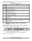
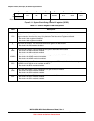
4 Reserved, should be cleared.
3
PPDF
Partial Power-Down Flag. This read-only status bit indicates that the MCU has recovered from stop2 mode.
0 MCU has not recovered from stop2 mode.
1 MCU recovered from stop2 mode.
2
PPDACK
Partial Power-Down Acknowledge. Writing a 1 to PPDACK clears the PPDF bit.
1
PPDE
Partial Power-Down Enable. The write-once PPDE bit can be used to lockout the partial power-down feature. This
is a write-once bit.
0 Partial power-down is not enabled.
1 Partial power-down is enabled and controlled via the PPDC bit.
0
PPDC
Partial Power-Down Control. The PPDC bit controls which power-down mode is selected. This bit cannot be set
if LPR is set. If PPDC and LPR are set in a single write instruction, only PPDC is actually set. PPDE must be set
for PPDC to be set.
0 Stop3 low-power mode enabled.
1 Stop2 partial power-down mode enabled.
There are also restrictions on LVDE and LVDSE. See Ta bl e 3-1 for details.