


MCF51QE128 MCU Series Reference Manual, Rev. 3
Freescale Semiconductor 115
Get the latest version from freescale.com
Chapter 6 Parallel Input/Output Control
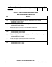
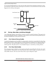
6.2.3 Port Drive Strength Select
An output pin can be selected to have high output drive strength by setting the corresponding bit in the
drive strength select register (PTxDSn). When high drive is selected, a pin is capable of sourcing and
sinking greater current. Even though every I/O pin can be selected as high drive, ensure that the total
current source and sink limits for the MCU are not exceeded. Drive strength selection is intended to affect
the DC behavior of I/O pins. However, the AC behavior is also affected. High drive allows a pin to drive
a greater load with the same switching speed as a low drive enabled pin into a smaller load. Because of
this, the EMC emissions may be affected by enabling pins as high drive.
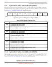
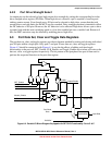
6.3 Port Data Set, Clear and Toggle Data Registers
The port data set, clear, and toggle registers provide an alternate method for setting and clearing individual
port I/O pins within a single port. Only port C and port E have data set, clear, and toggle registers.
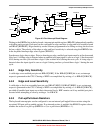
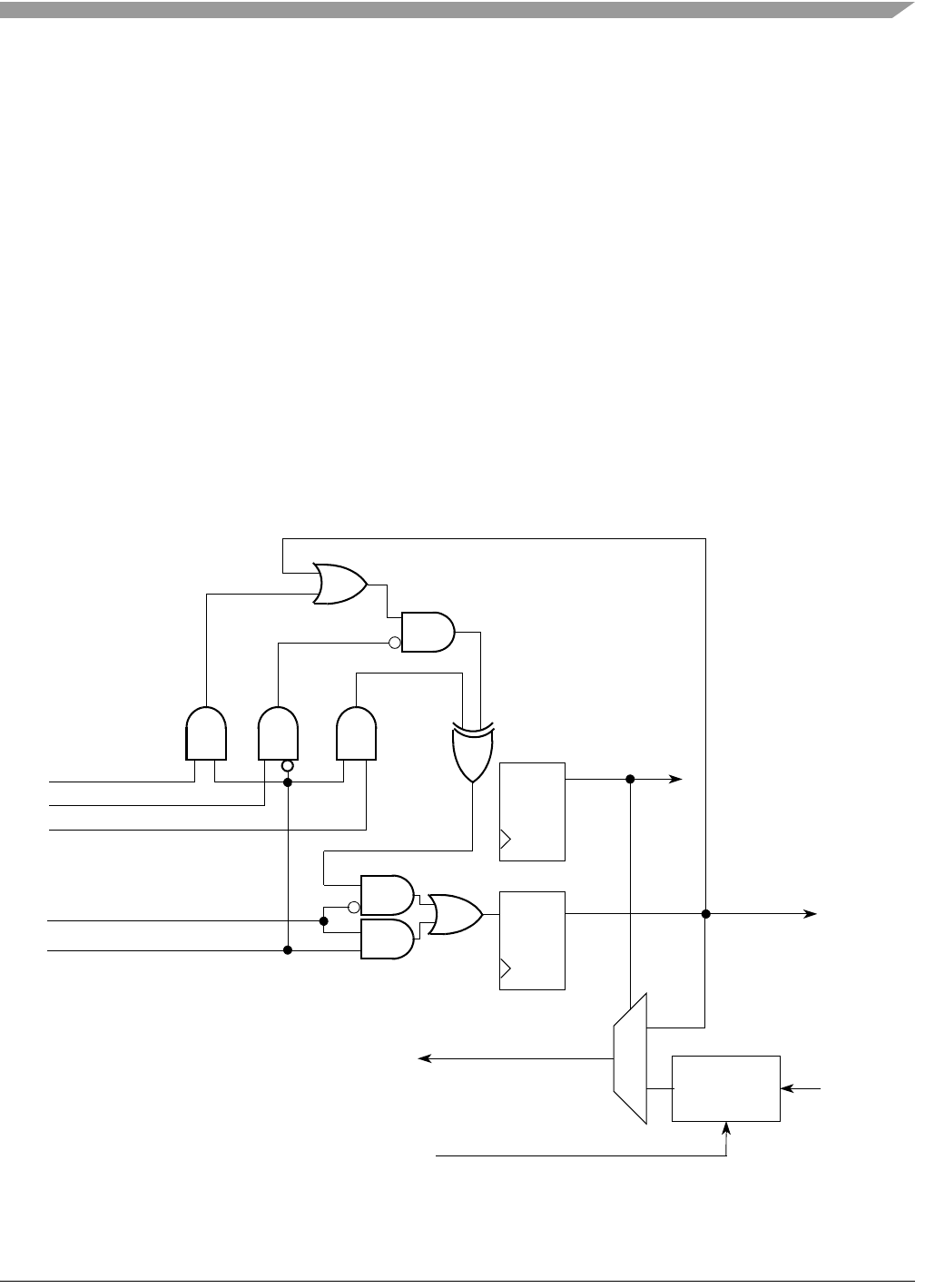
Figure 6-2 should be contrasted with Figure 6-1 to see the the effects of adding set/clear/toggle
functionality to the port cell. SET_Enable, CLR_Enable, and Toggle_Enable are set when you write to the
data set, clear, or toggle register, respectively. The bit pattern on the peripheral bus port is then used to
perform the requested function on the port data register.
Figure 6-2. Parallel I/O Block Diagram Equipped with SET/CLR Functionality: Ports C & E
QD
QD
1
0
Port Read
PTxDDn
PTxDn
Output Enable
Output Data
Input Data
Synchronizer
Data
BUSCLK
DATA
SET_Enable
CLR_Enable
Module_Enable
TOGGLE_Enable