


Chapter 18 Version 1 ColdFire Debug (CF1_DEBUG)
MCF51QE128 MCU Series Reference Manual, Rev. 3
370 Freescale Semiconductor
Get the latest version from freescale.com
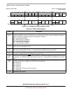
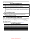
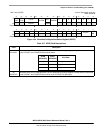
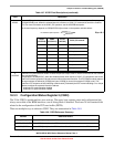
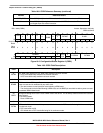
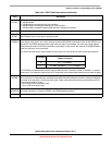
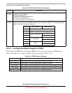
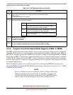
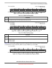
18.3.4 Configuration/Status Register 3 (CSR3)
CSR3 contains the BDM flash clock divider (BFCDIV) value in a format similar to HCS08 devices.
There are multiple ways to reference CSR3. They are summarized in Table 18-10.
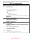
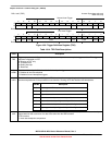
4–3
PSTBRM
PST trace buffer recording mode. Defines the trace buffer recording mode. The start and stop recording conditions
are defined by the PSTBSS field.
00 Normal recording mode
01 Continuous, normal recordingReserved
10 PC profile recordingReserved
11 Continuous PC profile recordingReserved
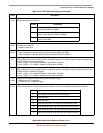
2–0
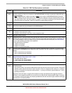
PSTBSS
PST trace buffer start/stop definition. Specifies the start and stop conditions for PST trace buffer recording. In
certain cases, the start and stop conditions are defined by the breakpoint registers. The remaining breakpoint
registers are available for trigger configurations.
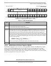
Table 18-10. CSR3 Reference Summary
Method Reference Details
READ_CSR3_BYTE Reads CSR3[31
–24] from the BDM interface. Available in all modes.
WRITE_CSR3_BYTE Writes CSR3[31–24] from the BDM interface. Available in all modes.
READ_DREG Reads CSR3[31–0] from the BDM interface. Classified as a non-intrusive BDM command.
WRITE_DREG Writes CSR3[31–0] from the BDM interface. Classified as a non-intrusive BDM command.
WDEBUG Instruction No operation during the core’s execution of a WDEBUG instruction
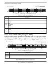
Table 18-9. CSR2 Field Descriptions (continued)
Field Description
PSTBSS Start Condition Stop Condition
000 Trace buffer disabled, no recording
001 Unconditional recording
010
ABxR{& DBR/DBMR}
PBR0/PBMR
011 PBR1
100
PBR0/PBMR
ABxR{& DBR/DBMR}
101 PBR1
110
PBR1
ABxR{& DBR/DBMR}
111 PBR0/PBMR