


Timer/PWM Module (S08TPMV3)
MCF51QE128 MCU Series Reference Manual, Rev. 3
348 Freescale Semiconductor
Get the latest version from freescale.com
The bus rate clock is the main system bus clock for the MCU. This clock source requires no
synchronization because it is the clock used for all internal MCU activities including operation of the CPU
and buses.
In MCUs that have no PLL or the PLL is not engaged, the fixed system clock source is the same as the
bus-rate-clock source, and it does not go through a synchronizer. When a PLL is present and engaged, a
synchronizer is required between the crystal divided-by-two clock source and the timer counter. This
means counter transitions are properly aligned to bus-clock transitions. A synchronizer is used at chip level
to synchronize the crystal-related source clock to the bus clock.
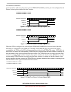
The external clock source may be connected to any TPM channel pin. This clock source always has to pass
through a synchronizer to assure that counter transitions are properly aligned to bus clock transitions. The
bus-rate clock drives the synchronizer; therefore, to meet Nyquist criteria even with jitter, the frequency
of the external clock source must not be faster than the bus rate divided-by four. With ideal clocks, the
external clock can be as fast as bus clock divided by four.
When the external clock source shares the TPM channel pin, this pin should not be used for other channel
timing functions. For example, it would be ambiguous to configure channel 0 for input capture when the
TPM channel 0 pin was also being used as the timer external clock source. It is your responsibility to avoid
such settings. The TPM channel could be used in output compare mode for software timing functions (pin
controls set not to affect the TPM channel pin).
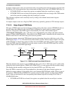
17.4.1.2 Counter Overflow and Modulo Reset
An interrupt flag and enable are associated with the 16-bit main counter. The flag (TOF) is a
software-accessible indication that the timer counter has overflowed. The enable signal selects between
software polling (TOIE = 0) where no hardware interrupt is generated or interrupt-driven operation
(TOIE = 1) where a static hardware interrupt is generated whenever TOF is set.
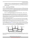
The conditions causing TOF to become set depend on whether the TPM is configured for center-aligned
PWM (CPWMS = 1). In the simplest mode, there is no modulus limit and the TPM is not in center-aligned
PWM mode. In this case, the 16-bit timer counter counts from 0x0000 through 0xFFFF and overflows to
0x0000 on the next counting clock. TOF is set at the transition from 0xFFFF to 0x0000. When a modulus
limit is set, TOF is set at the transition from the value set in the modulus register to 0x0000. When the TPM
is in center-aligned PWM mode (CPWMS = 1), the TOF flag is set as the counter changes direction at the
end of the count value set in the modulus register (at the transition from the value set in the modulus
register to the next lower count value). This corresponds to the end of a PWM period (the 0x0000 count
value corresponds to the center of a period).
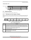
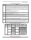
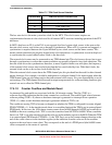
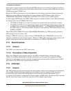
Table 17-7. TPM Clock Source Selection
CLKSB:CLKSA TPM Clock Source to Prescaler Input
00 No clock selected (TPM counter disabled)
01 Bus rate clock
10 Fixed system clock
11 External source