


ColdFire Core
MCF51QE128 MCU Series Reference Manual, Rev. 3
158 Freescale Semiconductor
The notion of a software IACK refers to the ability to query the interrupt controller near the end of an
interrupt service routine (after the current interrupt request has been cleared) to determine if there are any
pending (but currently masked) interrupt requests. If the response to the software IACK’s byte operand
read is non-zero, the service routine uses the value as the vector number of the highest pending interrupt
request and passes control to the appropriate new handler. This process avoids the overhead of a context
restore and RTE instruction execution followed immediately by another interrupt exception and context
save. In system environments with high rates of interrupt activity, this mechanism can improve overall
performance noticeably.
Emulation of the S08’s 1-level IRQ processing can easily be managed by software convention within the
ColdFire interrupt service routines. For this type of operation, only two of the seven interrupt levels are
used:
• SR[I] equals 0 indicates interrupts are enabled
• SR[I] equals 7 indicates interrupts are disabled
Recall that ColdFire treats true level 7 interrupts as edge-sensitive, non-maskable requests. Typically, only
the IRQ input pin and a low-voltage detect are assigned as level 7 requests. All the remaining interrupt
requests (levels 1-6) are masked when SR[I] equals 7. In any case, all ColdFire processors guarantee that
the first instruction of any exception handler is executed before interrupt sampling resumes. By making
the first instruction of the ISR a store/load status register (
STLDSR #0x2700) or a move-to-SR
(MOVE.W #2700,SR) instruction, interrupts can be safely disabled until the service routine is exited with an
RTE instruction that lowers the SR[I] back to level 0. The same functionality can also be provided without
an explicit instruction by setting CPUCR[IME] since this forces the processor to load SR[I] with 7 on each
interrupt exception.
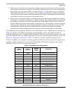
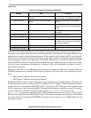
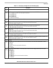
Table 7-9. Exception Processing Comparison
Attribute S08 V1 ColdFire
Exception Vector Table 32, 2-byte entries, fixed location at upper end
of memory
103, 4-byte entries, located at lower end of
memory at reset, relocatable with the VBR
More on Vectors 2 for CPU + 30 for IRQs, reset at upper
address
64 for CPU + 39 for IRQs, reset at lowest
address
Exception Stack Frame 5-byte frame: CCR, A, X, PC 8-byte frame: F/V, SR, PC; General-purpose
registers (An, Dn) must be saved/restored by
the ISR
Interrupt Levels 1 = f(CCR[I]) 7 = f(SR[I]) with automatic hardware support
for nesting
Non-Maskable IRQ Support No Yes, with level 7 interrupts
Core-enforced IRQ Sensitivity No Level 7 is edge sensitive, else level sensitive
INTC Vectoring Fixed priorities and vector assignments Fixed priorities and vector assignments, plus
any 2 IRQs can be remapped as the highest
priority level 6 requests
Software IACK No Yes
Exit Instruction from ISR RTI RTE