


MCF51QE128 MCU Series Reference Manual, Rev. 3
302 Freescale Semiconductor
Get the latest version from freescale.com
5
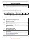
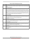
RDRF
Receive Data Register Full Flag. RDRF becomes set when a character transfers from the receive shifter into the
receive data register (SCIxD). To clear RDRF, read SCIxS1 with RDRF set and then read the SCI data register
(SCIxD).
0 Receive data register empty.
1 Receive data register full.
4
IDLE
Idle Line Flag. IDLE is set when the SCI receive line becomes idle for a full character time after a period of activity.
When ILT is cleared, the receiver starts counting idle bit times after the start bit. So if the receive character is all
1s, these bit times and the stop bit time count toward the full character time of logic high (10 or 11 bit times
depending on the M control bit) needed for the receiver to detect an idle line. When ILT is set, the receiver doesn’t
start counting idle bit times until after the stop bit. So the stop bit and any logic high bit times at the end of the
previous character do not count toward the full character time of logic high needed for the receiver to detect an
idle line.
To clear IDLE, read SCIxS1 with IDLE set and then read the SCI data register (SCIxD). After IDLE has been
cleared, it cannot become set again until after a new character has been received and RDRF has been set. IDLE
is set only once even if the receive line remains idle for an extended period.
0 No idle line detected.
1 Idle line was detected.
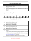
3
OR
Receiver Overrun Flag. OR is set when a new serial character is ready to be transferred to the receive data
register (buffer), but the previously received character has not been read from SCIxD yet. In this case, the new
character (and all associated error information) is lost because there is no room to move it into SCIxD. To clear
OR, read SCIxS1 with OR set and then read the SCI data register (SCIxD).
0 No overrun.
1 Receive overrun (new SCI data lost).
2
NF
Noise Flag. The advanced sampling technique used in the receiver takes seven samples during the start bit and
three samples in each data bit and the stop bit. If any of these samples disagrees with the rest of the samples
within any bit time in the frame, the flag NF is set at the same time as RDRF is set for the character. To clear NF,
read SCIxS1 and then read the SCI data register (SCIxD).
0 No noise detected.
1 Noise detected in the received character in SCIxD.
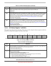
1
FE
Framing Error Flag. FE is set at the same time as RDRF when the receiver detects a logic 0 where the stop bit
was expected. This suggests the receiver was not properly aligned to a character frame. To clear FE, read
SCIxS1 with FE set and then read the SCI data register (SCIxD).
0 No framing error detected. This does not guarantee the framing is correct.
1 Framing error.
0
PF
Parity Error Flag. PF is set at the same time as RDRF when parity is enabled (PE = 1) and the parity bit in the
received character does not agree with the expected parity value. To clear PF, read SCIxS1 and then read the
SCI data register (SCIxD).
0 No parity error.
1 Parity error.
Table 15-5. SCIxS1 Field Descriptions (continued)
Field Description