


Chapter 18 Version 1 ColdFire Debug (CF1_DEBUG)
MCF51QE128 MCU Series Reference Manual, Rev. 3
412 Freescale Semiconductor
Get the latest version from freescale.com
loaded, which is indicated by the PST marker value immediately preceding the DDATA entry in the PSTB
that begins the address entries.
Multiple byte DDATA values are displayed in least-to-most-significant order. The processor captures only
those target addresses associated with taken branches that use a variant addressing mode (RTE and RTS
instructions and JMP and JSR instructions using address register indirect or indexed addressing modes,
and all exceptio vectors).
The simplest example of a branch instruction using a variant address is the compiled code for a C language
case statement. Typically, the evaluation of this statement uses the variable of an expression as an index
into a table of offsets, where each offset points to a unique case within the structure. For such
change-of-flow operations, the ColdFire processor loads the PSTB as follows:
1. Load PST=0x05 to identify that a taken branch is executed.
2. Optionally load the marker for the target address capture. Encodings 0x0D or 0x0E identify the
number of bytes loaded into the PSTB.
3. The new target address is optionally available into the PSTB. The number of bytes of the target
address loaded is configurable (2 or 3 bytes, where the encoding is 0x0D and 0x0E, respectively).
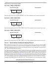
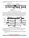
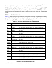
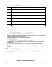
Another example of a variant branch instruction would be a JMP (A0) instruction. Figure 18-23 shows the
PSTB entries that indicate a JMP (A0) execution, assuming the CSR was programmed to display the lower
2 bytes of an address.
PST of 0x05 indicates a taken branch and the marker value 0x0D indicates a 2-byte address. Thus, the
following entries display the lower two bytes of address register A0 in least-to-most-significant nibble
order. The next PST entry after the JMP instruction completes depends on the target instruction. See
Section 18.4.3.2, “PST Trace Buffer (PSTB),” for entry descriptions explaining the 2-bit prefix before
each address nibble.
PST Values Description
0x05 Taken Branch
0x0D 2-byte Address
{10, Address[3:0]}
{10, Address[7:4]}
{10, Address[11:8]}
{10, Address[15:12]}
Figure 18-23. Example JMP Instruction Output in PSTB