


ColdFire Core
MCF51QE128 MCU Series Reference Manual, Rev. 3
Freescale Semiconductor 155
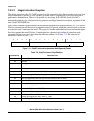
3. The processor saves the current context by creating an exception stack frame on the system stack.
The exception stack frame is created at a 0-modulo-4 address on top of the system stack pointed to
by the supervisor stack pointer (SSP). As shown in Figure 7-10, the processor uses a simplified
fixed-length stack frame for all exceptions. The exception type determines whether the program
counter placed in the exception stack frame defines the location of the faulting instruction (fault)
or the address of the next instruction to be executed (next).
4. The processor calculates the address of the first instruction of the exception handler. By definition,
the exception vector table is aligned on a 1 Mbyte boundary. This instruction address is generated
by fetching an exception vector from the table located at the address defined in the vector base
register. The index into the exception table is calculated as (4 × vector number). After the exception
vector has been fetched, the vector contents determine the address of the first instruction of the
desired handler. After the instruction fetch for the first opcode of the handler has initiated,
exception processing terminates and normal instruction processing continues in the handler.
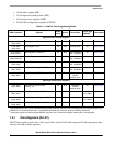
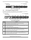
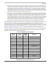
All ColdFire processors support a 1024-byte vector table aligned on any 1 Mbyte address boundary (see
Table 7-6). For the V1 ColdFire core, the only practical locations for the vector table are based at
0x(00)00_0000 in the flash or 0x(00)80_0000 in the RAM. The table contains 256 exception vectors; the
first 64 are defined for the core and the remaining 192 are device-specific peripheral interrupt vectors. See
Chapter 8, “Interrupt Controller (CF1_INTC)” for details on the device-specific interrupt sources.
For the V1 ColdFire core, the table is partially populated with the first 64 reserved for internal processor
exceptions, while vectors 64-102 are reserved for the peripheral I/O requests and the seven software
interrupts. Vectors 103–255 are unused and reserved.
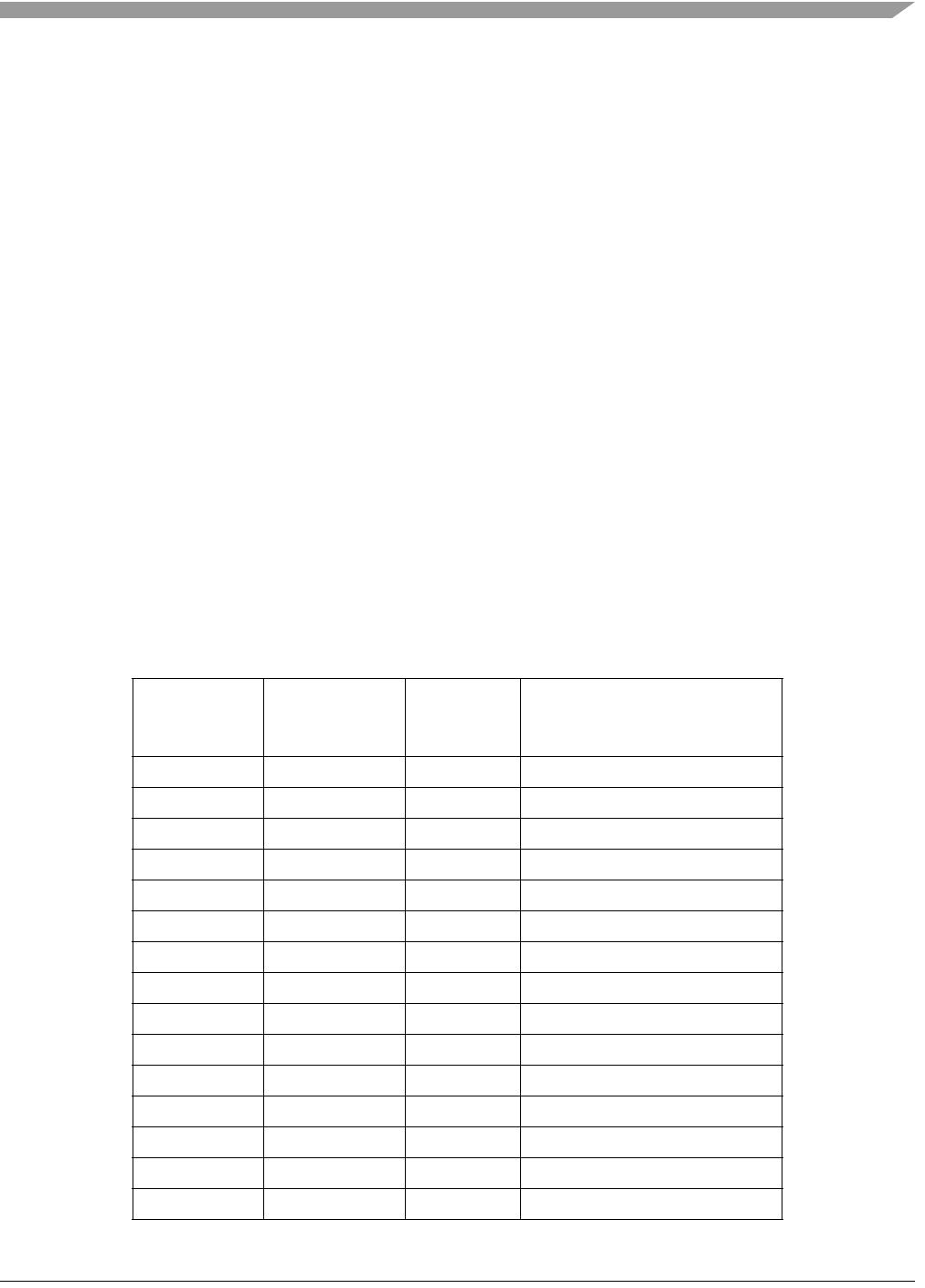
Table 7-6. Exception Vector Assignments
Vector
Number(s)
Vector
Offset (Hex)
Stacked
Program
Counter
Assignment
0 0x000 — Initial supervisor stack pointer
1 0x004 — Initial program counter
2 0x008 Fault Access error
3 0x00C Fault Address error
4 0x010 Fault Illegal instruction
5–7 0x014–0x01C — Reserved
8 0x020 Fault Privilege violation
9 0x024 Next Trace
10 0x028 Fault Unimplemented line-A opcode
11 0x02C Fault Unimplemented line-F opcode
12 0x030 Next Debug interrupt
13 0x034 — Reserved
14 0x038 Fault Format error
15–23 0x03C–0x05C — Reserved
24 0x060 Next Spurious interrupt