


MCF51QE128 MCU Series Reference Manual, Rev. 3
Freescale Semiconductor 181
Get the latest version from freescale.com
Chapter 8 Interrupt Controller (CF1_INTC)
NOTE
The requests associated with the INTC_FRC register have a fixed level and
priority that cannot be altered.
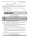
The INTC_PL6P7 register specifies the highest-priority, maskable interrupt request, which is defined as
the level six, priority seven request. The INTC_PL6P6 register specifies the second-highest-priority,
maskable interrupt request defined as the level six, priority six request. Reset clears both registers,
disabling any request re-mapping.
For an example of the use of these registers, see Section 8.6.2, “Using INTC_PL6P{7,6} Registers”.
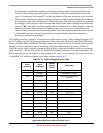
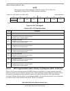
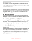
Figure 8-3. INTC_PL6P{7,6} Registers
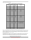
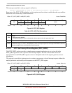
8.3.2.3 INTC Wake-up Control Register (INTC_WCR)
The interrupt controller provides a combinatorial logic path to generate a special wake-up signal to exit
from the wait or stop modes. The INTC_WCR register defines wake-up condition for interrupt recognition
during wait and stop modes. This mode of operation works as follows:
1. Write to the INTC_WCR to enable this operation (INTC_WCR[ENB]) and define the interrupt
mask level needed to force the core to exit the wait or stop mode (INTC_WCR[MASK]). The
maximum value of INTC_WCR[MASK] is 0x6 (0b110).
2. Execute a stop instruction to place the processor into wait or stop mode.
3. After the processor is stopped, the interrupt controller enables special logic that evaluates the
incoming interrupt sources in a purely combinatorial path; no clocked storage elements are
involved.
4. If an active interrupt request is asserted and the resulting interrupt level is greater than the mask
value contained in INTC_WCR[MASK], the interrupt controller asserts the wake-up output signal.
This signal is routed to the clock generation logic to exit the low-power mode and resume
processing.
Typically, the interrupt mask level loaded into the processor's status register field (SR[I]) during the
execution of the STOP instruction matches the INTC_WCR[MASK] value.
Offset: CF1_INTC_BASE + 0x18 (INTC_PL6P7)
CF1_INTC_BASE + 0x19 (INTC_PL6P6)
Access: Read/Write
76543210
R 0 0 0
REQN
W
Reset00000000
Table 8-5. INTC_PL6P{7,6} Field Descriptions
Field Description
7–5 Reserved, must be cleared.
4–0
REQN
Request number. Defines the peripheral IRQ number to be remapped as the level 6, priority 7 (for INTC_PL6P7)
request (priority 6 for INTC_PL6P6). The value must be in the 2–29 (0x2–0x1D) range; all other values are ignored.