


MCF51QE128 MCU Series Reference Manual, Rev. 3
52 Freescale Semiconductor
Get the latest version from freescale.com
Chapter 3 Modes of Operation
In addition to the above, upon waking up from stop2, SPMSC2[PPDF] is set. This flag is used to direct
user code to go to a stop2 recovery routine. PPDF remains set and the I/O pin states remain latched until
a 1 is written to SPMSC2[PPDACK].
Wakeup from stop2 can be initiated with an RTC interrupt. Unlike most other modules on the chip, the
RTC is not reset as a result of exiting stop2. This implies that the RTC interrupt is asserted (although
masked) upon exit from stop2.
To maintain I/O states for pins configured as general-purpose I/O before entering stop2, restore the
contents of the I/O port registers, which have been saved in RAM, to the port registers before writing to
the PPDACK bit. If the port registers are not restored from RAM before writing to PPDACK, the pins
switch to their reset states when PPDACK is written.
For pins that were configured as peripheral I/O, reconfigure the peripheral module that interfaces to the
pin before writing to PPDACK. If the peripheral module is not enabled before writing to PPDACK, the
pins are controlled by their associated port control registers when the I/O latches are opened.
3.8.1.1 Low-Range Oscillator Considerations for Stop2
If using a low-range oscillator during stop2, reconfigure the ICSC2 register before PPDACK is written.
The low-range oscillator (ICSC2[RANGE] = 0) can operate in stop2 as the clock source for the RTC
module. If the low-range oscillator is active when entering stop2, it remains active in stop2 regardless of
the value of ICSC2[EREFSTEN]. To disable the oscillator in stop2, switch the ICS into FBI or FEI mode
before executing the STOP instruction.
3.8.2 Stop3 Mode
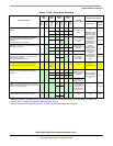
Stop3 mode is entered by executing a STOP instruction under the conditions as shown in Table 3-1. The
states of all of the internal registers and logic, RAM contents, and I/O pin states are maintained. The
on-chip regulator is placed in standby state.
Stop3 can be exited by asserting RESET or by an interrupt from one of the following sources: the RTC,
ADC, ACMP, IRQ, SCI, or KBI.
If stop3 is exited by the RESET
pin, the MCU is reset and operation resumes after taking the reset vector.
Exit by one of the internal interrupt sources results in the MCU taking the appropriate interrupt vector.
3.8.3 Stop4: Low Voltage Detect or BDM Enabled in Stop Mode
Stop4 is differentiated from stop2 and stop3 in that the on-chip regulator is fully engaged.
Entry into halt mode from run mode is enabled if the XCSR[ENBDM] bit is set. This register is described
in Chapter 18, “Version 1 ColdFire Debug (CF1_DEBUG)”. If ENBDM is set when the CPU executes a
STOP instruction, the system clocks to the background debug logic remain active when the MCU enters
stop mode. Because of this, background debug communication remains possible. If you attempt to enter
stop2 or stop3 with ENBDM set, the MCU enters stop4 instead (see Table 3-1 for details).