


MCF51QE128 MCU Series Reference Manual, Rev. 3
174 Freescale Semiconductor
Get the latest version from freescale.com
Chapter 8 Interrupt Controller (CF1_INTC)
8.1.1 Overview
Interrupt exception processing includes interrupt recognition, aborting the current instruction execution
stream, storing of an 8-byte exception stack frame in memory, calculation of the appropriate vector, and
passing control to the specified interrupt service routine.
Unless specifically noted otherwise, all ColdFire processors sample for interrupts once during each
instruction’s execution during the first cycle of execution in the OEP. Additionally, all ColdFire processors
use an instruction restart exception model.
The ColdFire processor architecture defines a 3-bit interrupt priority mask field in the processor’s status
register (SR[I]). This field, and the associated hardware, support seven levels of interrupt requests with the
processor providing automatic nesting capabilities. The levels are defined in descending numeric order
with 7 > 6 ... > 1. Level 7 interrupts are treated as non-maskable, edge-sensitive requests while levels 6–1
are maskable, level-sensitive requests. The SR[I] field defines the processor’s current interrupt level. The
processor continuously compares the encoded IRQ level from CF1_INTC against SR[I]. Recall that
interrupt requests are inhibited for all levels less than or equal to the current level, except the edge-sensitive
level 7 request, which cannot be masked.
Exception processing for ColdFire processors is streamlined for performance and includes all actions from
the detection of the fault condition to the initiation of fetch for the first handler instruction. Exception
processing is comprised of four major steps. The interrupt-specific actions are highlighted.
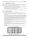
1. The processor makes an internal copy of the status register (SR) and enters supervisor mode by
setting SR[S] and disabling trace mode by clearing SR[T]. Interrupt exception also forces the
master mode (M) bit to be cleared and the interrupt priority mask (I) to be set to the level of the
current interrupt request.
2. The processor determines the exception vector number. For all faults except interrupts, the
processor performs this calculation based on the exception type. For interrupts, the processor
performs an IACK bus cycle to obtain the vector number from the interrupt controller if
CPUCR[IAE] equals 1. The IACK cycle is mapped to special locations within the interrupt
controller’s IPS address space with the interrupt level encoded in the address. If
CPUCR[IAE] equals 0, the processor uses the vector number supplied by the interrupt controller
at the time the request was signaled (for improved performance).
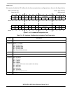
3. The processor saves the current context by creating an exception stack frame on the system stack.
As a result, exception stack frame is created at a 0-modulo-4 address on top of the system stack
defined by the supervisor stack pointer (SSP). The processor uses an 8-byte stack frame for all
exceptions. It contains the vector number of the exception, the contents of the status register at the
time of the exception, and the program counter (PC) at the time of the exception. The exception
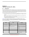
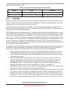
Software IACK No Yes
Exit Instruction from ISR RTI RTE
Table 8-1. Exception Processing Comparison (continued)
Attribute HCS08 V1 ColdFire