


Timer/PWM Module (S08TPMV3)
MCF51QE128 MCU Series Reference Manual, Rev. 3
Freescale Semiconductor 345
Get the latest version from freescale.com
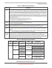
Table 17-5. TPMxCnSC Field Descriptions
Field Description
7
CHnF
Channel n flag. When channel n is an input-capture channel, this read/write bit is set when an active edge occurs
on the channel n pin. When channel n is an output compare or edge-aligned/center-aligned PWM channel, CHnF
is set when the value in the TPM counter registers matches the value in the TPM channel n value registers. When
channel n is an edge-aligned/center-aligned PWM channel and the duty cycle is set to 0% or 100%, CHnF is not
set even when the value in the TPM counter registers matches the value in the TPM channel n value registers.
A corresponding interrupt is requested when this bit is set and interrupts are enabled (CHnIE = 1). Clear CHnF
by reading TPMxCnSC while this bit is set and then writing a logic 0 to it. If another interrupt request occurs before
the clearing sequence is complete, CHnF remains set. This is done so a CHnF interrupt request is not lost due to
clearing a previous CHnF.
Reset clears this bit. Writing a logic 1 to CHnF has no effect.
0 No input capture or output compare event occurred on channel n
1 Input capture or output compare event on channel n
6
CHnIE
Channel n interrupt enable. This read/write bit enables interrupts from channel n. Reset clears this bit.
0 Channel n interrupt requests disabled (use for software polling)
1 Channel n interrupt requests enabled
5
MSnB
Mode select B for TPM channel n. When CPWMS is cleared, setting this bit configures TPM channel n for
edge-aligned PWM mode. Refer to the summary of channel mode and setup controls in Ta ble 1 7- 6.
4
MSnA
Mode select A for TPM channel n. When CPWMS and MSnB are cleared, MSnA configures TPM channel n for
input-capture mode or output compare mode. Refer to Table 17-6 for a summary of channel mode and setup
controls.
Note: If the associated port pin is not stable for at least two bus clock cycles before changing to input capture
mode, it is possible to get an unexpected indication of an edge trigger.
3–2
ELSnB
ELSnA
Edge/level select bits. Depending upon the operating mode for the timer channel as set by CPWMS:MSnB:MSnA
and shown in Table 17-6, these bits select the polarity of the input edge that triggers an input capture event, select
the level that is driven in response to an output compare match or select the polarity of the PWM output.
Clearing these bits configures the related timer pin as a general purpose I/O pin. This function is typically used to
temporarily disable an input capture channel or to make the timer pin available as a general purpose I/O pin when
the associated timer channel is set up as a software timer that does not require the use of a pin.
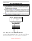
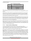
Table 17-6. Mode, Edge, and Level Selection
CPWMS MSnB:MSnA ELSnB:ELSnA Mode Configuration
XXX 00
Pin not used for TPM.
Revert to GPIO or other peripheral control
0
00
01
Input capture
Capture on rising edge only
10 Capture on falling edge only
11 Capture on rising or falling edge
01
01
Output compare
Toggle output on compare
10 Clear output on compare
11 Set output on compare
1X
10
Edge-aligned
PWM
High-true pulses
(clear output on compare)
X1
Low-true pulses
(set output on compare)