


ColdFire Core
MCF51QE128 MCU Series Reference Manual, Rev. 3
164 Freescale Semiconductor
7.3.3.14 Reset Exception
Asserting the reset input signal (RESET) to the processor causes a reset exception. The reset exception has
the highest priority of any exception; it provides for system initialization and recovery from catastrophic
failure. Reset also aborts any processing in progress when the reset input is recognized. Processing cannot
be recovered.
The reset exception places the processor in the supervisor mode by setting the SR[S] bit and disables
tracing by clearing the SR[T] bit. This exception also clears the SR[M] bit and sets the processor’s SR[I]
bit to the highest level (level 7, 0b111). Next, the VBR is initialized to zero (0x0000_0000). The control
registers specifying the operation of any memories (e.g., cache and/or RAM modules) connected directly
to the processor are disabled.
NOTE
Other implementation-specific registers are also affected. Refer to each
module in this reference manual for details on these registers.
After the processor is granted the bus, it performs two longword read-bus cycles. The first longword at
address 0x(00)00_0000 is loaded into the supervisor stack pointer and the second longword at address
0x(00)00_0004 is loaded into the program counter. After the initial instruction is fetched from memory,
program execution begins at the address in the PC. If an access error or address error occurs before the first
instruction is executed, the processor enters the fault-on-fault state.
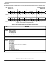
ColdFire processors load hardware configuration information into the D0 and D1 general-purpose
registers after system reset. The hardware configuration information is loaded immediately after the
reset-in signal is negated. This allows an emulator to read out the contents of these registers via the BDM
to determine the hardware configuration.
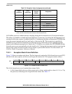
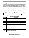
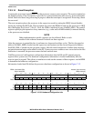
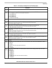
Information loaded into D0 defines the processor hardware configuration as shown in Figure 7-12.
BDM: Load: 0x60 (D0)
Store: 0x40 (D0)
Access: User read-only
BDM read-only
31 30 29 28 27 26 25 24 23 22 21 20 19 18 17 16
R PF VER REV
W
Reset110011110001 0000
15 14 13 12 11 10 9 8 7 6 5 4 3 2 1 0
R MAC DIVEMACFPUMMU000 ISA DEBUG
W
Reset 0 000000000101001
Figure 7-12. D0 Hardware Configuration Info