


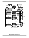
Timer/PWM Module (S08TPMV3)
MCF51QE128 MCU Series Reference Manual, Rev. 3
342 Freescale Semiconductor
Get the latest version from freescale.com
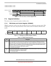
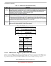
17.3.2 TPM Counter Registers (TPMxCNTH:TPMxCNTL)
The two read-only TPM counter registers contain the high and low bytes of the value in the TPM counter.
Reading either byte (TPMxCNTH or TPMxCNTL) latches the contents of both bytes into a buffer where
they remain latched until the other half is read. This allows coherent 16-bit reads in big-endian or
5
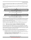
CPWMS
Center-aligned PWM select. When present, this read/write bit selects CPWM operating mode. By default, the TPM
operates in up-counting mode for input capture, output compare, and edge-aligned PWM functions. Setting
CPWMS reconfigures the TPM to operate in up/down counting mode for CPWM functions. Reset clears CPWMS.
0 All channels operate as input capture, output compare, or edge-aligned PWM mode as selected by the
MSnB:MSnA control bits in each channel’s status and control register.
1 All channels operate in center-aligned PWM mode.
4–3
CLKS[B:A]
Clock source selects. As shown in Table 17-3, this 2-bit field disables the TPM system or selects one of three clock
sources to drive the counter prescaler. The fixed system clock source is only meaningful in systems with a
PLL-based system clock. When there is no PLL, the fixed-system clock source is the same as the bus rate clock.
The external source is synchronized to the bus clock by TPM module, and the fixed system clock source (when a
PLL is present) is synchronized to the bus clock by an on-chip synchronization circuit. When a PLL is present but
not enabled, the fixed-system clock source is the same as the bus-rate clock.
2–0
PS[2:0]
Prescale factor select. This 3-bit field selects one of eight division factors for the TPM clock input as shown in
Ta bl e 1 7- 4. This prescaler is located after any clock source synchronization or clock source selection so it affects
the clock source selected to drive the TPM system. The new prescale factor affects the clock source on the next
system clock cycle after the new value is updated into the register bits.
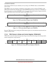
Table 17-3. TPM-Clock-Source Selection
CLKSB:CLKSA TPM Clock Source to Prescaler Input
00 No clock selected (TPM counter disable)
01 Bus rate clock
10 Fixed system clock
11 External source
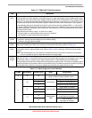
Table 17-4. Prescale Factor Selection
PS[2:0]
TPM Clock Source
Divided-by
000 1
001 2
010 4
011 8
100 16
101 32
110 64
111 128
Table 17-2. TPMxSC Field Descriptions (continued)
Field Description