


MCF51QE128 MCU Series Reference Manual, Rev. 3
Freescale Semiconductor 243
Get the latest version from freescale.com
Chapter 12
Internal Clock Source (S08ICSV3)
12.1 Introduction
The internal clock source (ICS) module provides clock source choices for the MCU. The module contains
a frequency-locked loop (FLL) as a clock source that is controllable by either an internal or an external
reference clock. The module can provide this FLL clock or either of the internal or external reference
clocks as a source for the MCU system clock.
The ICSTRM and FTRIM bits are normally reset to the factory trim values on any reset. However, any
reset that puts the device into BDM (a POR with the BKGD pin held low or a development tool setting
SBDFR[BDFR]) results in the ICSTRM and FTRIM bits being set to values of 0x80 and 0. When
debugging the MCU, the factory trim value can be used by copying the trim values from the Flash locations
shown in table 4-4.
There are also signals provided to control a low power oscillator (XOSCVLP) module to allow the use of
an external crystal/resonator as the external reference clock.
Whichever clock source is chosen, it is passed through a reduced bus divider (BDIV) which allows a lower
final output clock frequency to be derived.
12.1.1 External Oscillator
The external oscillator module (XOSCVLP) provides the external clock opitons to the ICS module. The
output of this submodule (OSCOUT) can be used as the real-time counter module (RTC) clock source.
12.1.2 Stop2 Mode Considerations
If you are using a low range oscillator during stop2, reconfigure the ICSC2 register (the oscillator control
bits) before PPDACK is written. The low range (RANGE=0) oscillator can operate in stop2 to be the clock
source for the RTC module. If the low range oscillator is active when entering stop2, it remains active in
stop2 regardless of the value of EREFSTEN. To disable the oscillator in stop2, switch the ICS into FBI or
FEI mode before executing the STOP instruction.
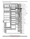
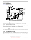
Figure 12-1 shows the MCF51QE128 Series block diagram with the ICS highlighted.