


Internal Clock Source (S08ICSV3)
MCF51QE128 MCU Series Reference Manual, Rev. 3
Freescale Semiconductor 251
Get the latest version from freescale.com
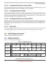
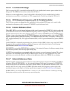
12.3.2 ICS Control Register 2 (ICSC2)
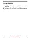
12.3.3 ICS Trim Register (ICSTRM)
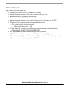
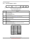
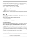
76543210
R
BDIV RANGE HGO LP EREFS ERCLKEN EREFSTEN
W
Reset:01000000
Figure 12-4. ICS Control Register 2 (ICSC2)
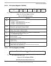
Table 12-4. ICSC2 Field Descriptions
Field Description
7:6
BDIV
Bus Frequency Divider. Selects the amount to divide down the clock source selected by the CLKS bits. This
controls the bus frequency.
00 Encoding 0 — Divides selected clock by 1
01 Encoding 1 — Divides selected clock by 2 (reset default)
10 Encoding 2 — Divides selected clock by 4
11 Encoding 3 — Divides selected clock by 8
5
RANGE
Frequency Range Select. Selects the frequency range for the external oscillator.
1 High frequency range selected for the external oscillator
0 Low frequency range selected for the external oscillator
4
HGO
High Gain Oscillator Select. The HGO bit controls the external oscillator mode of operation.
1 Configure external oscillator for high gain operation
0 Configure external oscillator for low power operation
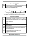
3
LP
Low Power Select. The LP bit controls whether the FLL is disabled in FLL bypassed modes.
1 FLL is disabled in bypass modes unless BDM is active
0 FLL is not disabled in bypass mode
2
EREFS
External Reference Select. The EREFS bit selects the source for the external reference clock.
1 Oscillator requested
0 External Clock Source requested
1
ERCLKEN
External Reference Enable. The ERCLKEN bit enables the external reference clock for use as ICSERCLK.
1ICSERCLK active
0 ICSERCLK inactive
0
EREFSTEN
External Reference Stop Enable. The EREFSTEN bit controls whether or not the external reference clock
remains enabled when the ICS enters stop mode.
1 External reference clock stays enabled in stop if ERCLKEN is set before entering stop
0 External reference clock is disabled in stop
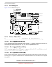
76543210
R
TRIM
W
Reset: Note: TRIM is loaded during reset from a factory programmed location when not in BDM mode. If in a BDM
mode, a default value of 0x80 is loaded.
Figure 12-5. ICS Trim Register (ICSTRM)