


MCF51QE128 MCU Series Reference Manual, Rev. 3
Freescale Semiconductor 289
Get the latest version from freescale.com
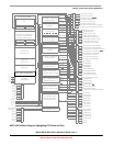
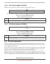
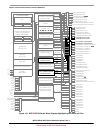
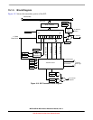
Figure 14-5. RTC Counter Overflow Example
In the example of Figure 14-5, the selected clock source is the internal clock source. The prescaler
(RTCPS) is set to 0x2 or divide-by-4. The modulo value in the RTCMOD register is set to 0x55. When the
counter, RTCCNT, reaches the modulo value of 0x55, the counter overflows to 0x00 and continues
counting. The real-time interrupt flag, RTIF, sets when the counter value changes from 0x55 to 0x00. A
real-time interrupt is generated when RTIF is set, if RTIE is set.
’b00the clock ofthe clock of flip-flop is
14.5 Initialization/Application Information
This section provides example code to give some basic direction to a user on how to initialize and
configure the RTC module. The example software is implemented in C language.
The example below shows how to implement time of day with the RTC using the 1-kHz clock source to
achieve the lowest possible power consumption. Because the 1-kHz clock source is not as accurate as a
crystal, software can be added for any adjustments. For accuracy without adjustments at the expense of
additional power consumption, the external clock (ERCLK) or the internal clock (IRCLK) can be selected
with appropriate prescaler and modulo values.
/* Initialize the elapsed time counters */
Seconds = 0;
Minutes = 0;
Hours = 0;
Days=0;
/* Configure RTC to interrupt every 1 second from 1-kHz clock source */
RTCMOD.byte = 0x00;
RTCSC.byte = 0x1F;
/**********************************************************************
Function Name : RTC_ISR
0x55
0x550x540x530x52 0x00 0x01
RTCMOD
RTIF
RTCCNT
RTC Clock
(RTCPS = 0x2)
Internal 1-kHz
Clock Source