


MCF51QE128 MCU Series Reference Manual, Rev. 3
Freescale Semiconductor 285
Get the latest version from freescale.com
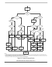
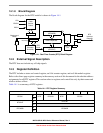
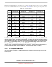
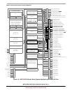
14.1.8 Block Diagram
The block diagram for the RTC module is shown in Figure 14-1.
Figure 14-1. Real-Time Counter (RTC) Block Diagram
14.2 External Signal Description
The RTC does not include any off-chip signals.
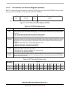
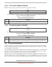
14.3 Register Definition
The RTC includes a status and control register, an 8-bit counter register, and an 8-bit modulo register.
Refer to the direct-page register summary in the memory section of this document for the absolute address
assignments for all RTC registers.This section refers to registers and control bits only by their names and
relative address offsets.
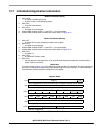
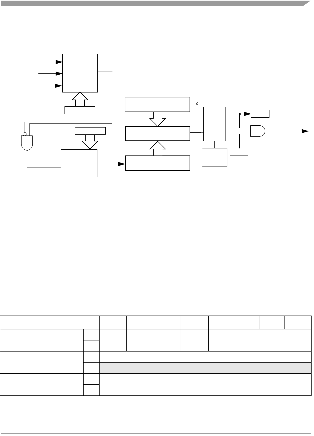
Table 14-1 is a summary of RTC registers.
Table 14-1. RTC Register Summary
Name
7 6 5 4 3210
RTCSC
R
RTIF RTCLKS RTIE RTCPS
W
RTCCNT
R RTCCNT
W
RTCMOD
R
RTCMOD
W
Clock
Source
Select
Prescaler
Divide-By
8-Bit Counter
(RTCCNT)
8-Bit Modulo
(RTCMOD)
8-Bit Comparator
RTIF
RTIE
Background
V
DD
RTC
Interrupt
Request
D
Q
R
E
LPO
RTC
Clock
Mode
ERCLK
IRCLK
RTCLKS
Write 1 to
RTIF
RTCPS
RTCLKS[0]